background image

GB

ENGLISH  |    ADV-F11

11

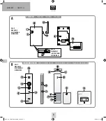
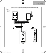
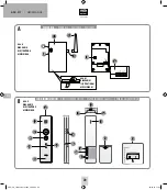
1.   The DECT power box must be opened before installation. No tools 

are required as the casing is only clicked together. Simple press the 
tab on the bottom inwards slightly and then lift the casing lid off 
the box as shown in figure A1.

2.   Hold the back section with one hand and mark the holes with a 

suitable pen.

3.   Lay the back section to one side and drill the holes 
  with a 6 mm drill.
4.   Insert the included dowels into the holes and screw the back 

section on.

5.   Connect the antenna to the power box. It has a screw connection 

for this purpose.  

NOTE

: To optimize the range, you can place the antenna at a different 

location using a separately available antenna extension.

COMMISSIONING

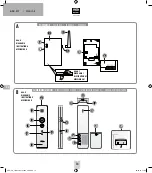
When the power box and the outdoor unit have been powered, the red 

power LED (4a) on the DECT power box will light up.

Inserting or replacing the battery

Open the battery compartment by pushing it down. Insert the battery 
into the socket in the battery slot with a small plug. The plug will only 
fit one way into the socket. Do not forcefully push the plug, so as not to 
damage the device.
When the battery needs to be changed, simply remove the old battery, 
and insert the new one.
Then push the battery compartment lid (23) onto the unit until it snaps 
into place.

Connecting the charger / charging the battery

The charger is connected to the power grid via the enclosed power 
supply. The LED on the charger lights up red to indicate that the supply 
voltage is connected.
To charge the battery in the device, simply place the mobile indoor unit 
into the charging unit.
While the battery is charging, the LED above the battery icon on the 
handset lights up blue (it does not matter whether the handset is on 
or off). When the battery is fully charged, the blue LED goes off. The 
handset may remain in the charging unit even when it is fully charged.

Switching handset on and off

The on/off switch for the handset is located at the bottom of the 
handset, between the two charging contacts. Turn the switch to „ON“ 
to turn it on, or „OFF“ to turn it off. The LED below the mute icon lights 
up blue when the ringtone is activated and the handset is connected to 

the power box. If the handset is not connected to the power box, no LED 
lights up when the handset is on. If the LED is flashing, the power box 
is switched off or out of range.

NOTE

: In case of a longer absence (of several days), the handset 

should be turned off and removed from the charging unit.  

OPERATION

You can connect the power once all components have been installed, 
first at the outdoor station and the DECT power box and then at the 
DECT indoor station. 
The red power LED (4a) should then light up on the DECT power box. 
On the DECT indoor station, the status LED (20) should first flash 
alternately red/blue and then light permanently after a short time. The 
system is then ready for operation and the bell can be activated at the 
outdoor station.

Procedure

1.   Press the bell button on the outdoor station
2.   The blue LED (4b) on the DECT power box flashes and the indoor 

station(s) play(s) the set ring melody. 

3.   Within 60 seconds, the press to talk button (17) can be pressed 

and a conversation held with the visitor. All other indoor stations 
immediately stop ringing.  

4.   Any door opener that is connected to the outdoor station can be 

activated during the conversation by pressing the door opener 
button (19).

5.   To end the conversation, press the press to talk button once (17).

Note

: after approximately 60 seconds, the DECT indoor station 

automatically switches back to standby mode. 

Set the ring melody 

To change the ringtone, proceed as follows:
1.   Open the battery compartment by pushing it down.
2.   Press the ringtone key to play the next tune (10).
3.   Once the desired tune has been played, put the battery compart-

ment lid back onto the device.

Set the volume of the ring melody

To adjust the ringtone volume, proceed as follows:
1.   Open the battery compartment by sliding the battery compartment 

lid (23) down.

2.   Press the plus button to increase the volume; press the minus 

button to decrease the volume.

3.   Once the desired volume has been set, put the battery compart-

ment lid back onto the device.

ADV-F11_I-Manual_210x240_Fin2.indd   11

29.04.15   11:24

Summary of Contents for ADV-F11

Page 1: ...ADV F11 ADV F11 EX BETRIEBSANLEITUNG OPERATING INSTRUCTIONS MODE D EMPLOI GEBRUIKSAANWIJZING ADV F11_I Manual_210x240_Fin2 indd 1 29 04 15 11 23...

Page 2: ...A1 DIAGRAM A1 ILLUSTRATION A1 AFBEELDING A1 A 3 4b 4a 5 18 1 6 POWERBOX POWER BOX POWERBOX POWERBOX Abb B DIAGRAM B ILLUSTRATION B AFBEELDING B B 9 14 14 21 16 18 12 15 17 13 19 20 2 11 22 23 FUNK IN...

Page 3: ...DEUTSCH ADV F11 3 Abb C DIAGRAM C ILLUSTRATION C AFBEELDING C C ANSCHLUSS DIAGRAMM CONNECTION DIAGRAM SCH MA DE RACCORDEMENT AANSLUITSCHEMA OPTIONAL ADV F11_I Manual_210x240_Fin2 indd 3 29 04 15 11 2...

Page 4: ...dadurch optimal ausgerichtet werden Die DECT Powerbox hat jeweils zwei Anschl sse GND 15V und Audio Diese sind parallel geschaltet Sie wird ber drei Adern mit der Au en station verbunden s dazu auch d...

Page 5: ...n Standby Betrieb zur ck WICHTIG HINWEIS Bevor Sie die DECT Powerbox und die Innenstation fest einbauen sollten Sie sie provisorisch an Ihren jeweiligen Montageorten in Betrieb nehmen um sich zu verge...

Page 6: ...kann Dazu gehen Sie wie folgt vor 1 Halten Sie die Pairing Taste 18 der Powerbox f r 5 Sekunden gedr ckt die blaue LED blinkt dann 2 Dr cken Sie jetzt 7mal auf die Pairing Taste der Powerbox die blaue...

Page 7: ...Haftung Bei Sach oder Personensch den die durch unsachgem e Handha bung oder Nichtbeachten der Sicherheitshinweise verursacht werden bernehmen wir keine Haftung In solchen F llen erlischt jeder Garant...

Page 8: ...DING A1 A 3 4b 4a 5 18 1 6 POWERBOX POWER BOX POWERBOX POWERBOX Abb B DIAGRAM B ILLUSTRATION B AFBEELDING B B 9 14 14 21 16 18 12 15 17 13 19 20 2 11 22 23 FUNK INNENSTATION WIRELESS INDOOR STATION ST...

Page 9: ...ENGLISH ADV F11 9 Abb C DIAGRAM C ILLUSTRATION C AFBEELDING C C ANSCHLUSS DIAGRAMM CONNECTION DIAGRAM SCH MA DE RACCORDEMENT AANSLUITSCHEMA OPTIONAL ADV F11_I Manual_210x240_Fin2 indd 9 29 04 15 11 2...

Page 10: ...and ringtone On Off 22 Charging unit 23 Battery compartment lid INSTALLATION NOTE When expanding a VISTADOOR system please disconnect it from mains before connecting the DECT power box with the syste...

Page 11: ...witch to ON to turn it on or OFF to turn it off The LED below the mute icon lights up blue when the ringtone is activated and the handset is connected to the power box If the handset is not connected...

Page 12: ...onsumption approx 170mA 50mA Temperature range 10 C to 50 C Dimensions 88mm x 150mm x 25mm Mobile indoor unit Operating voltage 3 7 V 600mAh Li Ion battery Standby time approx 48 h Temperature range 1...

Page 13: ...tutory rights are not affected by this guarantee Please note No claim can be made under guarantee in the following circumstances Operational malfunction Empty batteries or faulty accumulator Erroneous...

Page 14: ...DING A1 A 3 4b 4a 5 18 1 6 POWERBOX POWER BOX POWERBOX POWERBOX Abb B DIAGRAM B ILLUSTRATION B AFBEELDING B B 9 14 14 21 16 18 12 15 17 13 19 20 2 11 22 23 FUNK INNENSTATION WIRELESS INDOOR STATION ST...

Page 15: ...FRAN AIS ADF F11 15 Abb C DIAGRAM C ILLUSTRATION C AFBEELDING C C ANSCHLUSS DIAGRAMM CONNECTION DIAGRAM SCH MA DE RACCORDEMENT AANSLUITSCHEMA OPTIONAL ADV F11_I Manual_210x240_Fin2 indd 15 29 04 15 11...

Page 16: ...n visuel de la sonnerie 16 Touche silencieux pour d sactiver la sonnerie 17 Touche de communication 18 Touche de pairage 19 Touche d ouverture de la porte 20 DEL contr le du chargement 21 DEL d tat Po...

Page 17: ...ut tre soit suspendue au moyen d une vis unique comme sur l illustration soit install e de mani re fixe au moyen des trous de fixation qui se situent dans chacun des quatre coins de l appareil Les c b...

Page 18: ...de la m lodie souhait e il suffit de replacer le capot du compartiment de batterie sur l appareil R gler le volume de la m lodie Pour r gler le volume de la m lodie proc der comme suit 1 Ouvrir le co...

Page 19: ...techniques et d quipement Nettoyage et entretien D brancher du secteur les appareils aliment s sur secteur avant le nettoyage retirer la fiche La surface du bo tier peut tre nettoy e l aide d un chiff...

Page 20: ...LDING A1 A 3 4b 4a 5 18 1 6 POWERBOX POWER BOX POWERBOX POWERBOX Abb B DIAGRAM B ILLUSTRATION B AFBEELDING B B 9 14 14 21 16 18 12 15 17 13 19 20 2 11 22 23 FUNK INNENSTATION WIRELESS INDOOR STATION S...

Page 21: ...EDERLANDS ADV F11 21 Abb C DIAGRAM C ILLUSTRATION C AFBEELDING C C ANSCHLUSS DIAGRAMM CONNECTION DIAGRAM SCH MA DE RACCORDEMENT AANSLUITSCHEMA OPTIONAL ADV F11_I Manual_210x240_Fin2 indd 21 29 04 15 1...

Page 22: ...NG Voordat u de DECT Powerbox en het binnenstation definitief installeert dient u de appa raten eerst provisorisch op de gewenste plaats in bedrijf te stellen om er zeker van te zijn dat het bereik vo...

Page 23: ...nden als indicatie dat de stroomvoorziening is aangesloten Voor het laden van de accu in het apparaat zet u het mobiele interne station gewoon in de oplaadhouder Tijdens het laden van de accu brandt d...

Page 24: ...or het deksel omlaag te schuiven 2 Druk op de melodietoets 10 om telkens de daaropvolgende melodie af te spelen 3 Is de melodie die werd afgespeeld de door u gewenste dan doet u het deksel weer op het...

Page 25: ...eiligheidsrichtlijnen veroorzaakt wordt zijn wij niet aansprakelijk In deze gevallen vervalt elke aanspraak op garantie Gebruik dit product niet in ziekenhuizen of soortgelijke medische instel lingen...

Page 26: ...ADV F11_I Manual_210x240_Fin2 indd 26 29 04 15 11 24...

Page 27: ...ADV F11_I Manual_210x240_Fin2 indd 27 29 04 15 11 24...

Page 28: ...immung mit den grundlegenden Anforderungen und den brigen einschl gigen Bestimmungen befindet Die KONFORMIT TSERKL RUNG kann unter folgender Adresse gefunden werden http www m e de download ce adv f11...

Reviews: