IM 685-1
15
Grasp the rod and while applying some thrust to the rod in
the direction of the actuator to take up any free play, and
with the bracket in alignment with the linkages that connect
to it, tighten the two set screws. Return the actuator to the
minimum rate position.
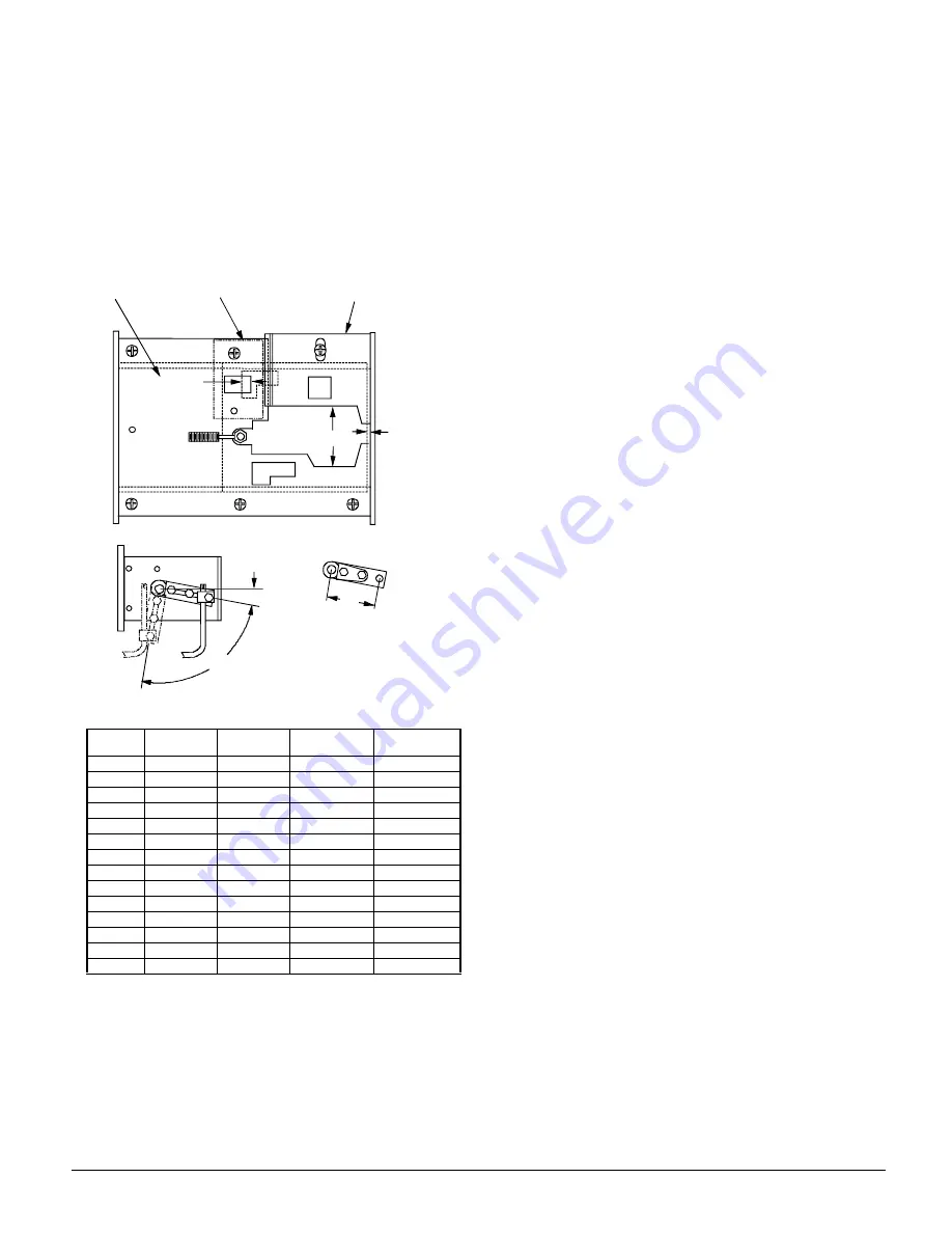
The adjustable plate (2), Figure 10a is positioned to provide
an opening per dimension "F".
Figure 10. Air and Gas Control Linkage
Actuator Crankarm
The actuator crankarm should not require adjustment. The
radius indicated by "G" dimension, Figure 10b will result in a
complete stroke from minimum to maximum, and provide the
correct amount of over travel to bottom out the linkage
bracket at the minimum rate position. Do not attempt to mod-
ify firing rates, etc. by changing the radius of the crackarm.
Switch Adjustment
Switches LS1 and LS2 prove maximum and minimum posi-
tion of the control rod. These switches are located in the con-
trol box switch compartment and have a limited range of
adjustment. When the two nuts that secure the switches are
loosened the switch will pivot on the inner stud and the outer
stud can be moved up and down. The switches should be
adjusted such that when the collar mounted on the actuator
rod is moved into position and pushes in the lever on the
switch, the switch will click to the "made" position, but the
lever will not bottom out against the switch body. When
properly adjusted the lever can move an additional 0.02
inches, as proven by slipping a feeler gauge between the
switch lever and the collar when in the "made" position. The
collar on the control rod should be adjusted so the switch
lever it is actuating will rest squarely on the outer surface of
the collar but only 0.03 inches from the edge. If the collar is
located for an engagement that is longer than 0.03 inches,
the collar may not reach the actuator on the other switch
when at the other end of its stroke.
Altitude Considerations
For altitudes of 2000 feet and higher, the gas burner must be
derated 4% for every 1000 feet of altitude.
Example: Model HT080 at an altitude of 3000 feet is derated
(0.04 x 3 = 0.12). At 1000 mbh input (1000 x 0.12 = 120
mbh), the actual input is (1000 - 120 = 880 mbh) at 3000 feet.
The method of derating the burner is to reduce the manifold
pressure. Multiply the Maximum Rate Manifold Pressure
shown under Column 8 in Table 5 by the following altitude
factors:
2000 feet = 0.845
5000 feet = 0.640
3000 feet = 0.774
6000 feet = 0.578
4000 feet = 0.706
7000 feet = 0.518
Model
HT***
D
E
F
G
020
.005
.116
.50
3.30
025
.005
.125
.83
3.30
032
.005
.101
.82
3.30
040
.005
.101
1.25
3.30
050
.020
.099
1.25
3.30
064
.020
.136
1.60
3.30
065
.020
.136
1.60
3.30
079
.020
.106
1.88
3.30
080
.020
.106
1.88
3.30
100
.020
.110
2.44
3.30
110
.020
.136
1.05
4.28
140
.020
.136
3.30
4.28
150
.020
.140
3.30
4.28
200
.020
.140
4.40
4.28
90º
10º
G
MIN
RATE
c
PROFILE
PLATE
d
ADJUSTABLE
PLATE
e
PRIMARY AIR
COLLECTOR
E
F
D
Figure 10b
Summary of Contents for SuperMod IM-685-1
Page 27: ...IM 685 1 27 Notes ...


