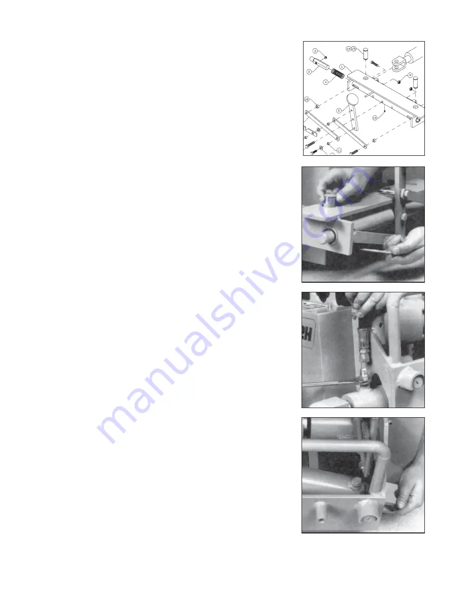
front of the machine frame.
7. Remove the clevis pin.
8. Unscrew the hydraulic line nut of the metal hydrau-
lic line that goes to the front of the cylinder to be
removed. Catch oil in a rag. Clean up oil from
floor, work area and machine.
9. Loosen the nut on the other end of the hydraulic
line. This nut is connected to a tee (Fig. 4, #18).
10. Rotate the metal line 90 degrees so that it is
pointed up.
11. Disconnect the hydraulic line nut that connects to
the rear port of the cylinder. Catch oil in a rag.
Clean up oil spillage.
12. Remove the fitting from the rear port of the cylin-
der (Photo #13).
13. Tilt the cylinder up at the free end and pull cylinder
toward the front of the machine (Photo #14).
14. Remove the 90 degree hydraulic fitting from the
front cylinder port.
15. Clean all fittings that have been removed or
disconnected. Replace all damaged fittings.
16. Slide the new cylinder into place. Note that the rod
end must be toward the back of the machine.
17. Apply pipe sealant to the front port fitting. DO NOT
ALLOW PIPE SEALANT TO GET INTO THE
INTERIOR OF THE FITTING.
18. Screw in fitting and tighten. Fitting should point
toward opposite end of the cylinder.
19. Slide rod end of the cylinder into the hole of the
machine frame with the ports pointed up.
20. Slide front clevis onto machine frame.
21. Rotate the metal hydraulic line to line up parallel
with the cylinder.
22. Reconnect metal line to front port fitting.
23. Tighten nut on the other end of the hydraulic line
onto the tee (Fig. 4, #18).
24. Apply pipe sealant to the rear port fitting.
25. Screw fitting into port and tighten.
26. Connect hose to fitting.
27. Align the holes of the clevis with frame hole and
slip clevis pin into front cylinder clevis. Add hitch
pin.
28. Rotate the dog plate and align the hole of the dog
plate with the holes of the rod end clevis. Add
hitch pin.
29. Check all hydraulic fittings (entire hydraulic sys-
tem). Tighten as required.
30. Set the machine on the track.
31. Connect the boring machine to a hydraulic power
source. Start the power source (refer to power
source operators manual for safe operating instruc-
tions).
32. Make sure the dog pins of the dog plate are both
locked into place.
33. Extend the cylinders to full stroke.
34. Shut off the power source.
35. Screw out the 1/2” square head bolts on the dog
Fig. 3
12
13
14
9.5.0
Fig. 3
Summary of Contents for McL-12HB ZIPPER
Page 6: ...CARRIAGE ASSEMBLY McL 12HB ZIPPER 3 1 0...
Page 8: ...DOG PLATE ASSEMBLY McL 12HB ZIPPER 4 1 0...
Page 10: ...MASTER TRACK ASSEMBLY McL 12HB ZIPPER 5 1 0...
Page 12: ...HOSES FITTINGS McL 12HB ZIPPER 6 1 0...
Page 14: ...CONTROL VALVE OPERATION McL 12HB ZIPPER 7 0 0 Rotation Lever Thrust Lever Thrust Gauge...


