
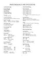
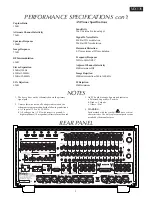

PERFORMANCE SPECIFICATIONS con’t
MX136
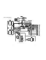
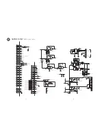
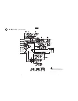
1. The heavy lines on the schematic denote the primary
signal path.
2. Unless otherwise noted, all voltages indicated on the
schematics are measured under the following conditions:
a. AC input at 120 volts, 50/60Hz.
b. All voltages are +/-10% with respect to ground. A
high impedance (10 megaohm) voltmeter must be used.
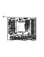
3. On PC board drawings, Square pad indicates:
a. Polarized Capacitors - Positive
b. Diodes - Cathode
c. Others - Pin 1
4. WARNING
Parts marked with the symbol have critical
characteristics. Use only replacement parts recom-
mended by the manufacturer.
NOTES
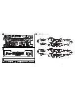
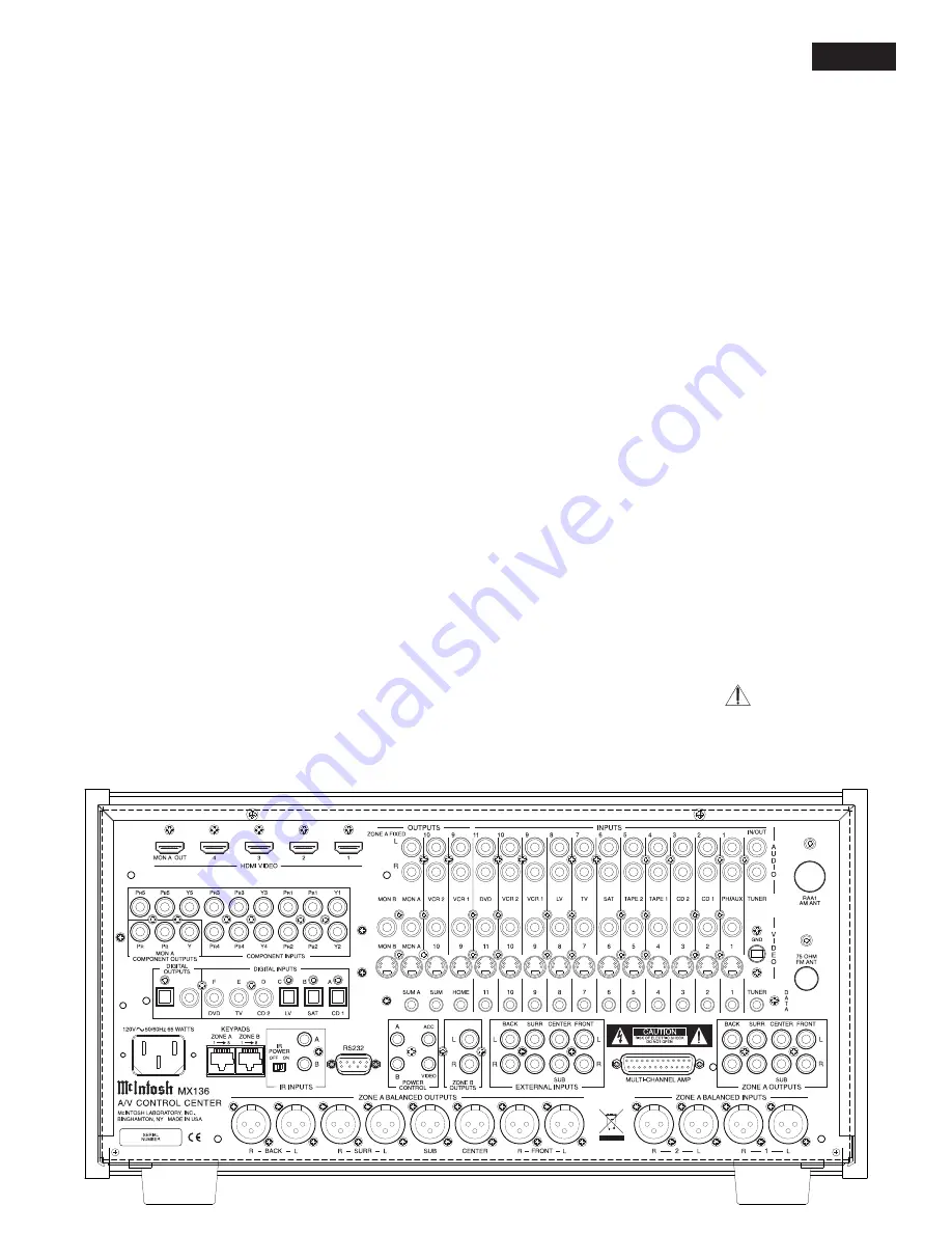
REAR PANEL
3
Capture Ratio
1.2dB
Alternate Channel Selectivity
75dB
Spurious Response
100dB
Image Response
75dB
RF Intermodulation
65dB
Stereo Separation
45dB at 100Hz
45dB at 1,000Hz
35dB at 10,000Hz
SCA Rejection
65dB
AM Tuner Specifications
Sensitivity
20uV External Antenna Input
Signal To Noise Ratio
48dB at 30% modulation
58dB at 100% modulation
Harmonic Distortion
0.5% maximum at 50% modulation
Frequency Response
50Hz to 6kHz NRSC
Adjacent Channel Selectivity
45dB minimum IHF
Image Rejection
65dB minimum from 540 to 1600kHz
IF Rejection
80dB minimum
Summary of Contents for MX136
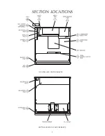
Page 4: ...4 SECTION LOCATIONS BOTTOM VIEW WITH COVER REMOVED TOP VIEW WITH COVER REMOVED ...
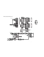
Page 5: ...MX136 5 6 BLOCK DIAGRAM ...
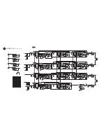
Page 6: ...7 8 BLOCK DIAGRAM con t ...
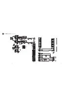
Page 7: ...9 11 10 INTERCONNECT MX136 1 ...
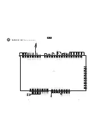
Page 8: ...12 14 13 DISPLAY 750565 SH 1 OF 2 2A BC ...
Page 9: ...15 17 16 DISPLAY 750565 SH 2 0F 2 MX136 2A BC ...
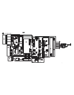
Page 11: ...SURROUND 750570 SH 2 OF 6 3 21 23 22 MX136 ...
Page 12: ...24 26 25 3 SURROUND 750570 SH 3 OF 6 ...
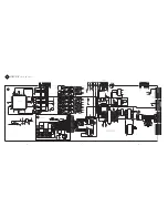
Page 13: ...MX136 27 28 SURROUND 750570 SCH 4 OF 6 3 ...
Page 14: ...29 30 SURROUND 750570 SCH 5 OF 6 3 ...
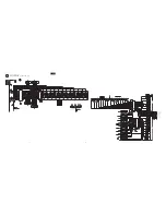
Page 15: ...MX136 SURROUND 750570 SCH 6 OF 6 3 31 32 ...
Page 16: ...SURROUND 750570 PCB 3 33 34 ...
Page 17: ...SURROUND 750570 PCB 3 33 34 ...
Page 18: ...MX136 35 36 NOTES ...
Page 19: ...37 38 DATA 750562 SCH 1 OF 2 4 ...
Page 20: ...39 41 40 DATA 750562 SH 2 OF 2 4 MX136 ...
Page 21: ...S VIDEO 750564 SH 1 OF 2 5 42 44 43 ...
Page 22: ...45 47 46 S VIDEO 750564 SH 2 OF 2 5 MX136 ...
Page 23: ...48 50 49 VIDEO 750563 6 ...
Page 24: ...51 53 52 INPUT 750561 SH 1 OF 2 7 MX136 ...
Page 25: ...54 56 55 INPUT 750561 SH 2 OF 2 7 INPUT 750561 7 ...
Page 26: ...COMPONENT VIDEO 750566 8 57 59 58 MX136 ...
Page 28: ...MX136 TUNER 049084 SCH 9A 63 64 ...
Page 29: ...TUNER 049084 PCB 65 66 RAA1 SECTION 049084 SCH and PCB 9A 9B ...
Page 30: ...MX136 BALANCED 750567 SCH 67 68 10 ...
Page 31: ...BALANCED 750567 PCB 10 69 70 ...
Page 32: ...MX136 HDMI MODULE 750623 11 71 ...
Page 33: ...HDMI POWER SUPPLY 750599 12 72 ...
Page 52: ...MX136 91 92 MX136 EXPLODED VIEW ...


