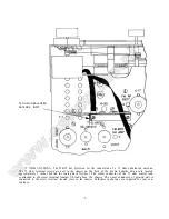
PUT IN 6 - 6 / 3 2 T H R E A D E D RODS
The tuner panel is now ready to he attached to the cabinet. The six threaded rods are inserted through
the two 5/32 inch and the four 3/16 inch holes in the cabinet panel. Secure the tuner panel to the cabinet
panel by installing on the rods the 6/32 "KEP" nuts supplied in the parts bag. Bring the nuts up tight with a
wrench or nut driver.
The tuner can now be installed in the cabinet. The tuner is secured to the cabinet shelf by the insertion
of the four 10/32 x 3/4 inch thumb screws supplied in the- parts bag through the 1/4 inch holes, in the shelf.
IMPORTANT: MAKE SURE THAT THE INNER CHASSIS FLOATS ON THE RUBBER SHOCK
MOUNTING FEET, AND DOES NOT CONTACT THE CABINET OR TUNER PANEL.
Next replace the felt washers and knobs.
Adequate ventilation is essential to the stable operation of any tuner. Do not put a solid back on the
cabinet behind the tuner. If the tuner is mounted vertically make sure sufficient ventilation is supplied.
Installation in the L-55 cabinet is done by the same procedure as for installation in a custom cabinet.
The cabinets are supplied with the cutouts and holes all prepared.
CONNECTING PROCEDURE
FM ANTENNA: In high signal strength areas a minimum antenna, such as the folded dipole supplied, is
all that is needed for local reception. Some care should be used in locating the folded dipole in a position that
is free as possible from local noise sources and shielding such as metal roofing and building framework. The
dipole should be mounted horizontally, and at 90° to the line of sight path to the transmitting stations.
In fringe areas a good antenna is required. A highly directional broad band antenna used in conjunction
with a rotor will result in superior performance in low signal strength areas.
—
5
—
www.eskonline.nl
Summary of Contents for MR-55
Page 17: ...w w w e s k o n l i n e n l...


