background image

23

Mute

Press the MUTE Push-button on the MP1100 Front 

Panel or the      MUTE Push-button on the Remote 

Control, to Mute the Audio in all outputs. The Front 

Panel Information Display will indicate the word 

MUTE. Refer to figure 97.

Pressing the MUTE Push-button a second time 

will unmute the MP1100.

Trim

Momentarily press the Front Panel INPUT Control to 

activate the MP1100 Trim Functions. Rotate the IN-

PUT Control to select the desired Trim Function and 

then use the LOAD Control to change the Trim Set-

ting. Refer to figure 60 on page 20 and Trim Functions 

on pages 19 thru 23. Using the Remote Contol press 

the TRIM Push-button to activate the Trim Mode. 

Then use the 

t


and


u


Push-buttons to select the 

TRIM Function and the 

p


and


q


Push-buttons on the 

Remote Control to change the Trim Setting. Approxi-

mately 6 seconds after Trim Function Selection and/or 

adjustments have stopped, the MP1100 will switch the 

Trim Mode Off.

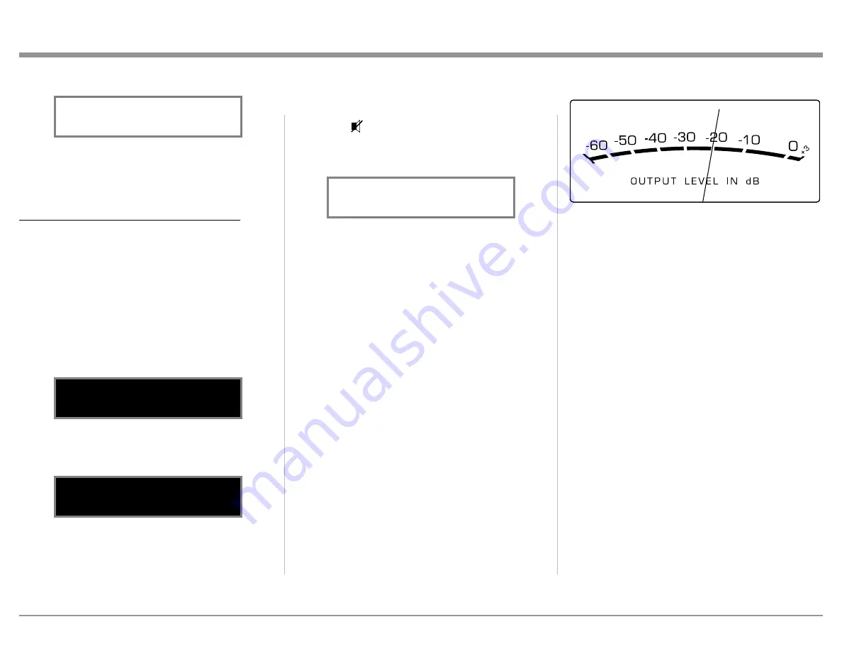
Output Meters

The MP1100 Output Meters indicate the Output Level 

in Decibels (dB) available at the Analog Connectors/

Jacks and Digital Connectors. Refer to figure 98.

The Meters are calibrated in dB (decibels) and respond 

to all the peaks contained in the musical information. 

A meter reading of 0dB indicates the MP1100 is deliv-

ering its rated output.

After approximately 6 seconds the Information 

Display returns to indicate the Source Selection and 

Settings.

INFORMATION DISPLAY ILLUMINATION

The Brightness Level of the MP1100 Front Panel In-

formation Display can be adjusted from bright to dim 

by performing the following:

1. Momentarily press the Front Panel INPUT Control 

(TRIM) or the TRIM Push-button on the Remote 

Control.

2. Rotate the Front Panel INPUT Control (TRIM) or 

press the 

t


and


u


Push-buttons on the Remote 

Control to select “DISPLAY,  BRIGHTNESS” as 

indicated on the Front Panel Information Display. 

Refer to figure 95.

3. Rotate the Front Panel LOAD Control or 

p


and


q


Push-buttons on the Remote Control to reduce the 

Brightness Level. Refer to figure 96.

After approximately 6 seconds the Information 

Display returns to indicate the Source Selection and 

Settings.

How to Operate the MP1100, con’t

Figure 94

   METER LIGHTS

       Off

Figure 96


DISPLAY

  BRIGHTNESS


Figure 95


DISPLAY

  BRIGHTNESS


Figure 97

MM    PHONO 1   RIAA

pF 50  MUTE Ohm=47K

Figure 98

Summary of Contents for MP1100

Page 1: ...McIntosh Laboratory Inc 2 Chambers Street Binghamton New York 13903 2699 Phone 607 723 3512 www mcintoshlabs com MP1100 Phono Preamplifier Owner s Manual...

Page 2: ...t of Microprocessors 25 Graphic Curves 27 28 Rumble and Scratch Filter Curves 28 Additional Information Photo 29 Specifications 30 Packing Instruction 31 Important Safety Information is supplied in a...

Page 3: ...e connected together Failure to do so could result in mal functioning of some or all of the system s normal operations When the MP1100 and other McIntosh Components are in their Standby Power Off Mode...

Page 4: ...as unbalanced Output connections for compatibility with a wide range of audio components Rumble and Scratch Filters Selectable Rumble and Scratch Filters can improve the quality of sound when playing...

Page 5: ...dio Components LED Front Panel Illumination The even Illumination of the Front Panel is accom plished by multiple extra long life Light Emitting Diodes LEDs arranged with a special orientation Glass F...

Page 6: ...formation on the next page pertaining to installing the MP1100 into cabinets 17 1 2 44 4cm 13 1 4 33 7cm 17 1 8 43 5cm 3 16 0 48cm 13 16 2 1cm 10 9 16 26 8cm 14 1 2 36 8cm 1 15 16 4 9cm 2 5 1cm Front...

Page 7: ...be retained for possible future use if the MP1100 is removed from the custom installation and used free standing The required panel cutout ventila tion cutout and unit dimensions are shown Always pro...

Page 8: ...e identification of Rear Panel Connections for the MP1100 Phono Preamplifier is located on a separate folded sheet contained in the Owner s Manual Packet Refer to separate sheet Mc1B for the Rear Pane...

Page 9: ...Optionally connect Audio Cables from the MP1100 PHONO 2 INPUT Jacks Left and Right to Turntable 2 Left and Right Output Jacks Note If Turntable 2 has Balanced XLR Output Con nectors and has a Phono Ca...

Page 10: ...Sensor receives commands from a Remote Control INPUT Control used to select a source for listening and recording The control is also used to enter the TRIM or SETUP Modes and select the various funct...

Page 11: ...n Display Indicates the current Phono Cartridge Capacitance Setting Indicates the current Input Source Selection Indicates the current Playback Equalizer Setting Indicates the current Phono Cartridge...

Page 12: ...etting use the u and t Push buttons to select the desired TRIM Function HR090 Remote Control Push Buttons Steps through the Phono Cartridge Capacitance Settings when one of the available PHONO Inputs...

Page 13: ...the Setup Mode 1 Press and hold in the INPUT Control to enter Setup Mode How to Operate the Setup Mode The Default Settings Chart below indicates the Func tion Name Default Setting and the Page Number...

Page 14: ...3 Input Refer to figure 5 9 To switch the PHONO 3 Input On rotate the LOAD Control until the display indicates SETUP PHONO 3 On Refer to figure 4 on page 13 10 Exit the SETUP Mode by several presses...

Page 15: ...he TRIM Profile Functions refer to How to Operate page 19 Refer to TRIM Functions starting on page 19 for selecting the desired Phono Resistance Capacitance Gain Sample Rate Stereo Mono Mode Settings...

Page 16: ...0 and 24 2 Rotate the LOAD Control to select SETUP Tube Lights Off Refer to figure 25 Note Illumination of Vacuum Tubes during the Warm Up period of time will continue when the Trim Setting for Tube L...

Page 17: ...gure 29 4 Exit the SETUP Mode by several presses of the INPUT Control Setup con t Power Mode Figure 28 SETUP Auto Off Enabled Figure 29 SETUP Auto Off Disabled Factory Reset If it becomes desirable to...

Page 18: ...Moving Coil Phono Cartridges Note Check the information supplied with the Phono Cartridge or with the Turntable if it was supplied with the Phono Cartridge already installed for the cartridge s imped...

Page 19: ...tting refer to figures 60 and 66 CARTRIDGE PROFILE There are four default Cartridge Profile Settings and the MP1100 has the ability to store up to five addition al Custom Cartidge Profile Settings Ref...

Page 20: ...dard known as LP using microgroove tech nology In 1956 the Record Industry Association of America RIAA established a new standard utilizing the LP microgroove technology along with a two part equaliza...

Page 21: ...ce unwanted Low Frequence Noise known as Rumble by using the MP1100 Rumble Filter To acti vate the Rumble Filter perform the following Steps 1 Select the desired PHONO Input Source Note Phono 1 was se...

Page 22: ...Information Display returns to indicate the Source Selection and Settings MONO STEREO MODE By default the Stereo Mode is active for all Input Sources however any Input Source may be assigned to Mono M...

Page 23: ...ctors Jacks and Digital Connectors Refer to figure 98 The Meters are calibrated in dB decibels and respond to all the peaks contained in the musical information A meter reading of 0dB indicates the MP...

Page 24: ...the McIntosh Web Site http www mcintoshlabs com us Support Pages Manuals aspx Under PRODUCT CATEGORY select Pre amplifiers then under MODEL NUMBER select MP1100 Click on SEARCH then select McIn tosh H...

Page 25: ...USB Audio Control Panel to be running unless it is de sired to make changes to the default settings 2 The McIntosh HD USB Audio Control Panel displays the current Sampling Rate Bit Rate and Buffer Siz...

Page 26: ...processors can be reset by per forming the following 1 Press and hold in the STANDBY ON Push button until all the Front Panel LEDs start flashing then release the STANDBY ON Push button 2 To switch th...

Page 27: ...increase the music playback time and reduce noise of a Record Disc several different Equal izer Curves have been used over the last 100 years When a master disc is created the volume level of the low...

Page 28: ...Hz 500Hz 1kHz 2kHz 5kHz 10kHz FREQUENCY 10Hz 45dB 5dB 40dB 35dB 30dB 25dB 20dB 15dB 10dB 5dB 0dB D E C I B E L 50dB 55dB MP1100 Rumble Filter Frequency Response 20Hz 20kHz 50Hz 100Hz 200Hz 500Hz 1kHz...

Page 29: ...29 Photo...

Page 30: ...anced Phono Equalization RIAA LP NAB AES or 78 Noise Filters Rumble 3dB at 50Hz Slope 24dB per Octave Scratch 3dB at 6 000Hz Slope 12dB per Octave Digital Outputs Coaxial Optical USB Digital Output Sa...

Page 31: ...hipping damage Use the original shipping carton and interior parts only if they are all in good serviceable condition If a shipping carton or any of the interior part s are needed please call or write...

Page 32: ...cts is the policy of McIntosh Laboratory Incorporated who reserve the right to improve design without notice Printed in the U S A McIntosh Laboratory Inc 2 Chambers Street Binghamton NY 13903 www mcin...

Reviews: