


The TAPE MONITOR switches are mechanically
interlocked to prevent simultaneous monitoring from
two tape recorders. If one button is at the IN position,
it must be pushed again to release it to the OUT posi-
tion before the other button can be pushed.
IMPORTANT: When the MAC 1900 is operated
with either MONITOR pushbutton in the IN position,
signal from any other source will not be heard from
the loudspeakers. To hear any other source, make
sure the pushbutton is in the OUT position.
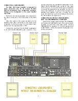
USING ONE TAPE RECORDER
The output of a tape recorder can be connected
to either TAPE MONITOR 1 or TAPE MONITOR 2 in-
put. The corresponding tape output of the MAC 1900
should then be connected to the input of the tape re-
corder. Any source can be recorded without being
affected by the tone control or volume control set-
tings. The playback of the tape recording can be
monitored by pushing the corresponding tape mon-
itor pushbutton.
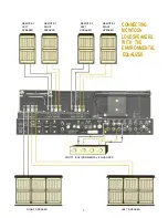
TWO TAPE RECORDERS
Two tape recorders can be used with the MAC
1900. Recordings can be made from recorder 1 to re-
corder 2, or from recorder 2 to recorder 1.
Example: Connect the output of recorder 1 to
TAPE MONITOR 1 input on the MAC 1900. Connect
the TAPE 1 OUTput on the MAC 1900 to the input of
recorder 1. In the same way, connect the output of
recorder 2 to TAPE MONITOR 2 input on the MAC
1900. Connect TAPE 2 OUTput of the MAC 1900 to
the input of recorder 2.
By setting the MAC 1900 INPUT selector switch at
TAPE 1, a recording can be made on tape recorder 2
from a tape playing on tape recorder 1. The record-
ing can be monitored by pushing the MONITOR
TAPE 2 button.
The tape recorder functions can be reversed by
setting the INPUT selector switch at TAPE 2. A re-
cording can then be made on tape recorder 1 from a
tape playing on tape recorder 2. The recording on
tape recorder 1 can be monitored by pushing the
MONITOR TAPE 1 button.
The MAC 1900 can also be used with one recorder
for recording other program sources while playing
tapes from a second recorder.
back by pushing the MONITOR TAPE 2 but-
ton. At the same time, the MAC 1900 can be
used to play a tape from tape recorder 1 by
releasing the monitor button for TAPE 2 and
pushing the monitor button for TAPE 1. The
signal of tape recorder 1 will then go to the
loudspeakers without affecting the recording
being made on tape recorder 2.
Tape recordings can be made simultane-
ously on two tape recorders by using PHONO
1, PHONO 2, FM, or AM as a program source.
Example:
Set the INPUT selector switch to the de-
sired source. The recording on either tape re-
corder can be monitored for playback by
pushing the appropriate tape monitor button.
CAUTION: When recording with two tape re-
corders at the same time from the same pro-
gram source, mutual interference of the re-
corder bias oscillators can result. This can
be heard as a howl or squeal in the back-
ground when the recordings are played back.
This noise is caused by insufficient filtering of
the bias oscillator circuits in the tape re-
corders. A test run should be made for the
particular recorders intended for this use.
FILTERS
L F (LOW FREQUENCY)
Use the L F filter switch to reduce objection-
able low-frequency noise created by a turntable
or record changer or acoustically coupled feed-
back.
OUT . . . filter disconnected.
IN . . . low-frequency signals below 50 Hz are
reduced when the switch is pushed to the IN
position.
H F (HIGH FREQUENCY)
Use the H F filter switch to reduce objection-
able high-frequency noise such as record scratch.
OUT . . . filter disconnected.
IN . . . rolls off response sharply at 7000 Hz.
MUTING
The muting circuit suppresses all noise between
FM stations. It suppresses all weaker stations not
strong enough to override the background noise.
The muting threshold setting determines the
strength of the signal which can be heard with muting
in operation. The muting threshold is carefully ad-
10
Example:
A recording from FM, AM, PHONO 1 or
PHONO 2 can be made on tape recorder 2 if
the INPUT selector switch is set to the cor-
responding source position. The recording on
tape recorder 1 can be monitored for play-
Summary of Contents for MAC 1900
Page 1: ...THE MAC 1900 SOLID STATE AM FM FM STEREO RECEIVER Price 1 25...
Page 2: ......
Page 16: ...14...
Page 17: ...15...
Page 18: ...16...
Page 23: ...Block Diagram 21...


