


12. IDE activity LED: IDELED
This connector connects to the hard disk activity indicator light on the case.
13. Turbo LED switch: TBLED
The motherboard‘s turbo function is always on. The turbo LED will remain constantly lit
while the system power is on. You may wish to connect the Power LED from the system
case to this lead. See the figure below.
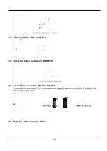
14. Reset switch lead: RST
This 2-pin connector connects to the case-mounted reset switch for rebooting your
computer without having to turn off your power switch. This is a preferred method of
rebooting in order to prolong the life of the system‘s power supply. See the figure below.
15. Keyboard lock switch lead: PWRLED
This 5-pin connector connects to the case-mounted key switch for locking the keyboard for
security purposes. See the figure below.
16. Speaker connector: SPEAKB
This 4-pins connector connects to the case-mounted speaker. See the figure below.
17. IR infrared module connector: IR1
This connector supports the optional wireless transmitting and receiving infrared module.
This module mounts to small opening on system cases that support this feature you must
also configure the setting through BIOS setup. Use the four pins as shown on the Back
View and connect a ribbon cable from the module to the motherboard according to the pin
definitions.
11