


19
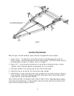
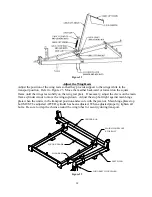
Figure 9
Harrow Configurations
McFarlane harrow sections may be attached in any one of several distinct configurations: 8-bar,
4+4-bar, 12-bar, 6+6-bar, 16-bar, and 8+8-bar. The 8, 12, and 16-bar harrow configurations
utilize a single set of pull points located adjacent to the center bar and wings. The 4+4, 6+6, and
8+8-bar harrow configurations (also known as dual sections) also utilize a second set of pull points
located at the rear end of the lift arms. Persons assembling an 8, 12, or 16-bar harrow should
ignore
the instructions in
italics
describing the attachment of the rear pull points. Those
assembling a dual section harrow should be sure to
follow
the instructions for attaching the rear
pull points in
italics
.
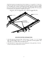
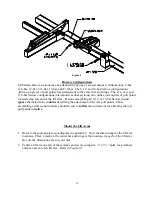
Mount the Lift Arms
1.
Refer to the appropriate layout diagram in appendix C. Note the dimensions for the lift arm
locations. Place a mark on the center bar and wings at the locations for each of the lift arms.
Be sure the dimensions are for your unit.
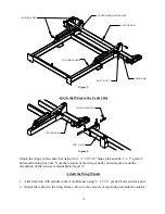
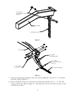
2.
Center a lift arm on each of these marks and secure using two ½” x 9 ½” bolts, lock washers,
and hex nuts for each lift arm. Refer to Figure 10.
Summary of Contents for HDL-1000 Series
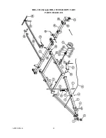
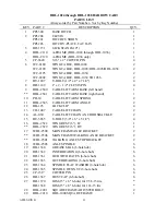
Page 32: ...APPENDIX B 32 HDL 1024 through HDL 1038 HARROW CART PARTS DIAGRAM...
Page 35: ...APPENDIX B 35 HDL 1040 THROUGH HDL 1050 HARROW CART PARTS DIAGRAM...
Page 38: ...APPENDIX B 38 HDL 1052 THROUGH HDL 1060 HARROW CART PARTS DIAGRAM...
Page 48: ...APPENDIX C 48...
Page 49: ...APPENDIX C 49...
Page 50: ...APPENDIX C 50...
Page 51: ...APPENDIX C 51...
Page 52: ...APPENDIX C 52...
Page 53: ...APPENDIX C 53...
Page 54: ...APPENDIX C 54...
Page 55: ...APPENDIX C 55...
Page 56: ...APPENDIX C 56...
Page 57: ...APPENDIX C 57...
Page 58: ...APPENDIX C 58...
Page 59: ...APPENDIX C 59...
Page 60: ...APPENDIX C 60...
Page 61: ...APPENDIX C 61...
Page 62: ...APPENDIX C 62...
Page 63: ...APPENDIX C 63...
Page 64: ...APPENDIX C 64...
Page 65: ...APPENDIX C 65...
Page 66: ...Notes...
Page 68: ......
Page 69: ......