background image


28 


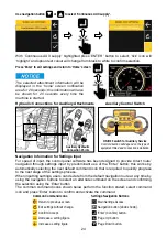
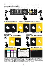
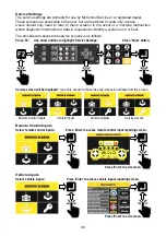
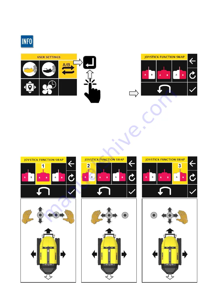
Joystick Function Swap & Travel Swap Settings  

Allows users to customise the joystick functions and/or machine forward travel direction for 
personal preference or to perform a specific task. 


Changes to these settings are only retained in the systems memory for the duration of the operating 
period - if the machine is switched off, all changes to the joystick and travel direction settings will 

revert to default; this is to ensure that controls operate in a familiar manner for all users at start-up. 


Highlight ‘Joystick 
Swap Settings’ and 
press ENTER’ 
button to access 
sub-menu of the 
joystick and travel 
swap settings. 


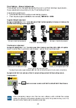
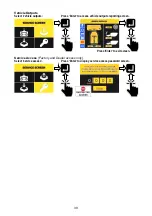
For joystick function swap refer to the settings below - if joystick function swap and travel direction swap is 
required refer to settings on the following page. 


Joystick Function Options for ‘Forward Drive’ Mode 
1.


LH Joystick operates Travel / RH Joystick operates Steering (Default). 

2.


LH Joystick operates Travel & Steering. 

3.


RH Joystick operates Travel & Steering. 


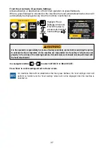
Joystick Function Swap Settings 

Use navigation buttons to highlight the custom joystick setting. 


Press ‘Enter’ to highlight ‘tick’, press ‘Enter’ again to confirm setting and exit to the ‘Home’ screen. 

Default: LH for Travel


/


RH for Steer 

LH Joystick operates Travel & Steer  

RH Joystick operates Travel & Steer 

Summary of Contents for Robocut RC56

Page 1: ...ROBOCUT Publication 930 January 2019 Part No 24214 30 Revision 22 03 19 McCONNEL Models RC56 RC75 REMOTE CONTROLLED TRACTOR UNIT Operator Manual...

Page 2: ...to verify that your machine has been registered with McConnel Limited IMPORTANT During the initial bedding in period of a new machine it is the customer s responsibility to regularly inspect all nuts...

Page 3: ......

Page 4: ...mple may require particular care when packing to avoid damage in transit 1 04 This warranty does not extend to any product from which McConnel Ltd s serial number plate has been removed or altered 1 0...

Page 5: ...d be undertaken within two days of the failure Claims submitted for repairs undertaken more than 2 weeks after a failure has occurred or 2 days after the parts were supplied will be rejected unless th...

Page 6: ...e deemed to be a waiver of any other term 4 02 If any provision of this limited warranty shall violate any applicable law and is held to be unenforceable then the invalidity of such provision shall no...

Page 7: ...tances to avoid the entrapment with human body parts BS EN ISO 14120 2015 Safety of machinery Guards general requirements for the design and construction of fixed and movable guards BS EN 4413 2010 Hy...

Page 8: ...e latest version of this manual please visit the manuals library on our website where an up to date version can be referenced online or downloaded http dealerinside mcconnel com dealerinside Parts PDF...

Page 9: ...it 16 Control Panel 19 Screen Access 20 Settings Menus 21 Job Timer Settings 21 Attachment Settings 22 Robo Aux 23 Float Settings Automatic Calibration 25 Float Settings Manual Adjustments 26 Front Ho...

Page 10: ...0 Undercarriage Components 51 Track Replacement 53 Track Removal Procedure 53 Support Springs 54 Reversible Fan 54 Emergency Control Unit Get Me Home 55 Charging Station For Remote Control Battery 56...

Page 11: ......

Page 12: ...portant or useful to emphasise LEFT HAND LH RIGHT HAND RH These terms are applicable to the machine when fitted to the tractor and viewed from the rear these terms also apply to tractor references SER...

Page 13: ...NE IDENTIFICATION Machine and engine identification plates are fitted to the left hand track plate of the machine in the locations indicated below a matching engine identification plate is also locate...

Page 14: ...per machine 4 4 8 Number of upper rollers per side per machine 1 1 2 Track width 230mm Number of links per side per machine 47 47 94 Chain pitch 72mm Track tensioner pressure Max 150Bar Total weight 4...

Page 15: ...tentiometer hydraulic power control from 0 to 100 Independent Cooling System for Hydraulic Circuits Self Cleaning Reversible Fan Customisable work and driving light system Proportional lift and lower...

Page 16: ...tentiometer hydraulic power control from 0 to 100 Independent Cooling System for Hydraulic Circuits Self Cleaning Reversible Fan Customisable work and driving light system Proportional lift and lower...

Page 17: ...g traffic from being hit by objects ejected at speed from the working flail head It should be noted that with the hinged hood opened objects could be thrown a considerable distance Being struck by a t...

Page 18: ...ce of the machine as stated in this manual The machine must only be used by a responsible adult who is familiar with all aspects relating to safe operation Certificated training may be required on cer...

Page 19: ...ect the work area prior to operation and remove stones glass metal wire or any other foreign objects that are hazardous Immovable hazards should be suitably marked so they can be easily avoided Take e...

Page 20: ...he machine or any mounted equipment Mounted equipment must always be switched off when manoeuvring outside of the work zone Personal Protective Equipment PPE We recommend that the following personal p...

Page 21: ...achine Handling The machine is equipped with overhead lifting points located on each side of the front and rear roll bars Access to the lifting points requires removal of the roll bar cover panels the...

Page 22: ...end of the track plates on both sides of the machine these positions should be used to fully secure the machine for transportation on flatbed vehicles or trailers Machine must be fully secured at all...

Page 23: ...cs Valves Rear Compartment Radiator Coolers Air Filter Antenna Exhaust Tool Mount Track Tensioner Drive Wheels Undercarriage Control Panel Engine ECU Isolator Fuses Relays Inclination Sensor Fuel Send...

Page 24: ...de View Engine Compartment Right Side View EGR Reversible Fan Alternator Exhaust System Battery Fan Belt Charge Air Hose Battery Fuel Filter Engine Oil Dipstick Fuel Pre Filter Oil Filter Engine Oil F...

Page 25: ...remote control unit and both sides of the machine in the locations indicated below E Stops are provided for use in an emergency situation only they must not be used as a shortcut method of switching o...

Page 26: ...m execution of the automatic or manual command and the following actions will occur Machine movement operations and functions will be immediately halted Engine will be immediately switched off Note af...

Page 27: ...ck Controls FORWARD TRAVEL REVERSE TRAVEL HOOD UP HOOD DOWN STEER RIGHT STEER LEFT TOOL DOWN TOOL UP Engine Speed Control RPM LCD Display EMERGENCY STOP Status Light Fan Control LH Joystick Forward Re...

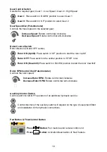
Page 28: ...ress Button Increase engine RPM Press Button Decrease engine RPM Steering Bias Dial Control for setting steering angle bias when operating on sloped ground Left Steering Bias Turn control dial to the...

Page 29: ...e rotor uphill Rotor OFF Place switch in the central position to STOP rotor Rotor ON Downhill Place switch in DOWN position to start the rotor downhill Rotor RPM Control Dial Potentiometer Controls th...

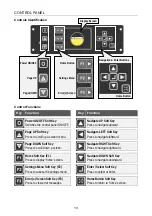
Page 30: ...to scroll down a screen Navigate RIGHT Soft Key Press to navigate rightward Home Soft Key F1 Press to display home screen Navigate DOWN Soft Key Press to navigate downward Settings Menu Soft Key F2 P...

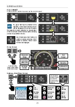
Page 31: ...rther screens Use directional arrow buttons to select an option and press enter button to confirm home screen will now be displayed Home Screen Settings Main Menu Screen User Settings Global Reset Ser...

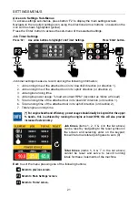
Page 32: ...power usage load at current RPM recorded as time at load 5 Total running time of the attached tool in its downhill direction or direction 1 6 Total running time of the attached tool in its uphill dire...

Page 33: ...B Reverse Scroll Page 1 Page 2 Page 3 Use navigation buttons and to scroll attachments list Highlight required attachment and press ENTER button to access sub menu of that attachment Use navigation b...

Page 34: ...home screen notification area for 20 seconds this information will also be shown for 20 seconds every time the machine is started Robo Aux Selecting ROBO AUX from the attachments list permits use of...

Page 35: ...from the default navigation route at any time by using the navigation buttons to select an alternate command on the screen and confirming the selection using the Enter button The common command icons...

Page 36: ...l site to accurately perform float calibration Highlight Float Settings and press ENTER button to access sub menu of float settings Use navigation buttons and to select the weight icon With the symbol...

Page 37: ...ighlight the or icon then press Enter button to scroll the LOW MED HI options Select and use Enter to scroll left to right and select and use Enter to scroll right to left Select to scroll options lef...

Page 38: ...on of front hood operation on grass flailheads When a grass flailhead is mounted on the machine the hood activate deactivate screen will automatically be displayed every time the machine is switched o...

Page 39: ...nd press ENTER button to access sub menu of the joystick and travel swap settings For joystick function swap refer to the settings below if joystick function swap and travel direction swap is required...

Page 40: ...ick setting and travel direction swap Press Enter to highlight tick press Enter again to confirm setting and exit to the Home screen When operating the machine with joystick and or travel direction sw...

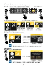
Page 41: ...and press ENTER button to access sub menu of the fan settings Press Enter to edit time Use navigation buttons to adjust displayed time Default setting is 5 minutes Set required time interval Options...

Page 42: ...screen Vehicle errors display screen If a vehicle error is displayed the cause should be checked and appropriate action taken to rectify the issue and clear the error The example error shown above RC...

Page 43: ...s Enter to access Machine Information screen Software details Firmware details Manufacture date QR code direct link to PDF operator manual Model Serial No Press Enter to exit screen The QR code on the...

Page 44: ...Verify when done Press Enter to exit screen Press Enter to access 500 hrs Checks information 500 Hour Service Checklist Service as listed every 500 Hours Verify when done Press Enter to exit screen Wh...

Page 45: ...digit Select first digit box Change to input mode Select first digit of code Set select mode Select second digit box Change to input mode Select second digit of code Set select mode Select third digi...

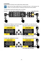
Page 46: ...n unaffected The procedure for performing global reset is as follows Press F2 Use arrow buttons to highlight Global Reset Press Enter button Reset screen will display a warning message you can decline...

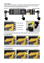
Page 47: ...Strobe light settings Light identification and status Use arrow buttons to select light symbol Enter button operates as toggle switch for ON and OFF Day Lights ON OFF Select day lights symbol Press En...

Page 48: ...s screen Strobe Light Pattern Selection Access to the strobe light setting is via the settings icon on the main lighting screen Select strobe light settings icon Press Enter to display the strobe ligh...

Page 49: ...e procedure to access the service screens is as follows Press F2 Use arrow buttons to highlight Service Settings Press Enter button Service screen will be displayed read only access to the service sub...

Page 50: ...ct vehicle outputs Press Enter to access vehicle outputs reporting screen Press Enter to exit screen Service Access Factory and Dealer access only Select service access Press Enter to display service...

Page 51: ...safety guarding is in good condition and fitted correctly Check nuts and bolts for tightness retighten if required Check track condition and tension re tension if required Check oil coolant and fuel l...

Page 52: ...illuminate in pulse mode to indicate the machine is switched on but not synchronised to the remote control unit On machines that are fitted with a Grass Flail Head the following safety warning stage i...

Page 53: ...until the engine starts Release switch when engine starts the switch will return to its central position Stopping the Engine Engine STOP Hold switch in DOWN position until the engine stops Release sw...

Page 54: ...ted and the gear speed potentiometer setting Gear 1 Low Speed 0 4 kph 2 5 mph Gear 2 High Speed 0 7 kph 4 5 mph Gear Control The machine has 2 gears to provide a choice of travel speeds in addition to...

Page 55: ...ment is performed using the steering bias dial Turn control dial to the left to select a desired degree of left steering bias Turn control dial to the right to select a desired degree of right steerin...

Page 56: ...en activated this feature provides 15 of horizontal float and advanced float that can be pre programmed to the user s desired settings Float setting information is accessed via User Settings on the ma...

Page 57: ...ea When operating this machinery you are responsible for your own safety and the safety of all others who enter the work area Working on Slopes When working on slopes do not operate from any position...

Page 58: ...ld be visually marked or avoided Ensure the work zone is clear of animals and persons Never manoeuvre the machine into an area where you can no longer clearly see it working Only work machinery in mat...

Page 59: ...ire Hazard Do not smoke near the machine Fuels oils and lubricants are flammable keep naked flames away from the machine at all times Track Protection In certain driving conditions or circumstances th...

Page 60: ...me situation can occur in reverse when a space is created between bearing roller idler roller and track To eliminate this risk track guides are provided on the front part of the undercarriage If the m...

Page 61: ...Standard Rubber Track 4500263 General duty low disturbance track Super Rubber Tracks 4500333 Deep tread rubber tracks for increased traction Steel Grouser Track 4500290 Rubber tracks with 46 steel gr...

Page 62: ...ort Block Fitment The rubber transport blocks have holes in them that locate on the spikes and are fitted by pushing them onto each set of accessible spikes before slowly driving the machine forward s...

Page 63: ...ed on a regular basis to ensure track tension is correctly maintained if track tension is too low there is a heightened risk of the track coming off whilst operating the machine if track tension is ex...

Page 64: ...bly supported Clean undercarriage components and the surrounding area of the machine prior to performing maintenance on this area of the machine Remove tensioner access panel 1 Loosen valve on tension...

Page 65: ...ting the pitch of the fan blades after a pre defined time By default the fan will reverse the airflow every 5 minutes if required the pre set time period can be changed via the machines control panel...

Page 66: ...allow transport of the machine in the event of a sudden breakdown or for diagnosing an issue with the controller When operated in this mode the machine will only travel at minimum speed and all other...

Page 67: ...is by simultaneous operation of buttons A D Counter rotation to the left is by simultaneous operation of buttons B C Raising the tool is by operation of button E Lowering the tool is by operation of b...

Page 68: ...material by turning the track in both directions while slackening slightly raise machine at same time if possible Oil leakage Hardened seals Gasket seals damaged or worn Clean around component and re...

Page 69: ...58 FUSES RELAYS The fuse box is mounted on the bulkhead in the front compartment of the machine...

Page 70: ...p 5A F14 PLC Electronics 2A F15 Remote Receiver 2A F16 E Stop LED Supply 2A F17 Glow Plugs 40A F18 Manual Override 15A F19 ECU Supply X1 15A F20 PLC Electronics CDC2000X 2A F21 2A F22 Sensors Supply 2...

Page 71: ......

Page 72: ...McConnel Limited Temeside Works Ludlow Shropshire SY8 1JL England Telephone 01584 873131 Facsimile 01584 876463 www mcconnel com...

Reviews: