background image


Installation and use 


7


MCK 3000 

3. System installation 


Figure 2. Overall dimensions 

Summary of Contents for AREA CONTROL MCK 3000

Page 1: ...AREA CONTROL MCK 3000 UNIVERSAL HECTARE COUNTER FOR AGRICULTURAL MACHINERY USE AND ASSEMBLY INSTRUCTIONS NO 201211MI REV 2 EN...

Page 2: ...ALY Tel 39 0425 754713 Fax 39 0425 741130 E mail mcstaff mcelettronica it Internet www mcelettronica it Manual code 201211MI Issued July 2012 Edition November 2020 MC elettronica S r l is not obliged...

Page 3: ...6 4 Accessories 16 4 1 Standard accessories 16 5 Setting the work parameters 17 5 1 Setting the working width 17 5 2 Setting the calibration of the feed rate 17 5 3 Setting the number of divisions of...

Page 4: ...ng the Monitor read the manual carefully and refer to it any time you have doubts on how to use the equipment or when you have to carry out maintenance operations The manual must be kept on the machin...

Page 5: ...e majeure events lightning floods fire or other causes which do not depend on MC elettronica Repairs under warranty which must be carried out in the laboratories of our authorised centres are entirely...

Page 6: ...ial worked area total worked area distance travelled speed Km h forecast of the hectares that will be worked in an hour only visible while you are working The Monitor uses a speed sensor to carry out...

Page 7: ...Installation and use 7 MCK 3000 3 System installation Figure 2 Overall dimensions...

Page 8: ...he bracket Figure 33 ref A and by means of two screws not supplied securely fasten the bracket to the structure fasten the Monitor to the bracket by screwing the supplied knobs Figure 33 ref B in the...

Page 9: ...rear of the agricultural machine vehicle or by creating a metal reference protruding by at least 7 mm Figure 4 ref B2 We recommend installing the speed sensor inside the wheel and placing the sensor...

Page 10: ...ts up as shown in the figure press keys and simultaneously 0 0 will appear on the Monitor cover 100 metres and the display will show the pulse count 1 2 3 etc once the 100 metres are covered confirm w...

Page 11: ...point of the switch by changing the number of links in the chain Figure 5 Installing the sensor in the lower part of the bar If necessary the switch can also be secured to the upper part of the bar by...

Page 12: ...the seed sensor in a stable way on the right or left side of the pipe using the bracket supplied with the lens facing the ground and the optical axis perpendicular to the ground at a distance of no m...

Page 13: ...trimmer A is turned to the extreme hourly position 2 Turn the monitor on The RED LED B must be on otherwise enhance the orientation or move the seed sensor closer 3 Turn the trimmer A very slowly cloc...

Page 14: ...the data relating to the working cycle The following elements can be seen on the panel REF DESCRIPTION A ON OFF key B LCD Display C Programming key D and keys E Forward speed forecast of workable hect...

Page 15: ...s you to set the parameter selected at that moment using the and keys by the indicator arrow total work width calibration of the feed rate number of sectors in which to split the bar Display key allow...

Page 16: ...ys the required parameters by the keys 3 Indicator arrows indicate the function selected for every key and 4 Accessories 4 1 Standard accessories Table 4 1 Standard accessories CODE DESCRIPTION PF0481...

Page 17: ...ntered to be saved 5 2 Setting the calibration of the feed rate Set the calibration of the feed rate C number of pulses coming from the speed sensor every 100 metres covered by the machine by turning...

Page 18: ...ount mode by turning the instrument on key and simultaneously pressing the and keys until parameter Ct appears on the display followed by a message indicating when the monitor will count the area The...

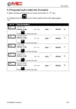
Page 19: ...ATA PROGRAMMING Current year Settable range 00 99 step 1 default 00 Press to confirm the data Current month Settable range 01 12 step 1 default 01 Press to confirm the data Current day Settable range...

Page 20: ...chanical counting sensor functions Check the operation of the mechanical sensor as follows 1 Turn the monitor on key 2 Select the partial total hectare display key 3 Pull the sensor chain so as to clo...

Page 21: ...idth By pressing the key again the Monitor also eliminates the second sector and continues to count the area with only 1 3 of the working width By pressing the key again the Monitor restores the total...

Page 22: ...he relative key must be kept pressed for more than 3 seconds and only with the machine stopped NOTE the totalisers are all independent of each other and therefore can be zeroed independently from each...

Page 23: ...instrument Clean the instrument with a wet cloth and mild detergent to avoid erasing the serigraphs on the panel Warning Do not use pressurised water jets Do not use abrasive products or solvents Do...

Page 24: ...cable is disconnected a Check the power cable SENSORS The speed sensor does not work a Broken cable b Calibration distance too long c Red part of sensor damaged a Restore connection b Adjust the cali...

Page 25: ...chanical vibrations resistance 2 G Operating conditions Room temperature 20 C 75 C Weather conditions Relative humidity 90 Transport and storage Temperature 25 C 85 C 9 2 Accessory technical data 9 2...

Page 26: ...MCK 3000 Installation and use MCK 3000 NOTES...

Page 27: ...Installation and use 27 MCK 3000...

Page 28: ...MCK 3000 Installation and use MCK 3000 Electronic equipment for agriculture earthmoving industry www mcelettronica it...

Reviews: