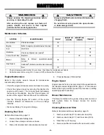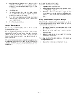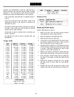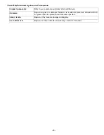
- 7 -
5.
Wash filter with low pressure water, Such as from a
garden hose. DO NOT use a high pressure sprayer.
If any holes or thin spots are apparent in filter, It must
be replaced.
6.
Let filters air dry.
7.
Put prefilter around filter, and slide into canister
housing. The rear of the filter is supported by a tab
welded to the back wall of canister.
8.
Install front cover making sure filter is straight and
seated against rear wall and cover. Tighten knob
snugly against cover.
9.
Install front cover and knob.
Sensor Maintenance
Sensor must be calibrated before first use. Sensor is NOT
calibrated at the factory.
Sensor programming mode is password protected. To enter
programming mode, remove cover of sensor and enter
“Mode, Mode, Up, Down, Up, Enter.” For non-intrusive
operation, see sensor manual. See Sensor manual for
further instructions.
The sensor is a sensitive piece of electronic equipment and
should be treated as such. DO NOT expose the sensor to
vibration. DO NOT expose to temperatures below -4° F or
above 122° F.
Sensor Relay/Alarm Testing
1.
Plug Electronics stand into VEU.
2.
Start engine after sensor warm-up is complete. Refer
to Starting Engine, page 5.
3.
Press test button on control panel. Engine should
shut down within seconds. Alarm and all lights should
activate. If it does not, Do Not use the VEU until it is
fixed.
Oiling the blower for long term storage
If the VEU will be stored more than one week without use, it
is required that the user oil the blower to prevent surface
corrosion or the internal vanes.
1.
Run the machine at idle, with the bypass valve in the
open position.
2.
Remove the small rubber cap located under the
vacuum gauge.
3.
Spray a light lubricating oil, such as WD-40 into the
hole for several seconds.
The spray must not contain silicone. Silicone may
damage the sensor.
4.
Replace the rubber cap and stop the machine.
Summary of Contents for VAPOR EXTRACTION UNIT
Page 13: ...10 This page intentionally left blank...
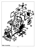
Page 15: ...12 Main Assembly...
Page 17: ...14 5 3 7 7 Canister and Blower Assembly...
Page 19: ...16 Sensor Stand Assembly...
Page 21: ...18 7 6 7 6 Control Assembly...
Page 23: ...20 5 5 1 7 5 Plug Assembly...
Page 25: ...22 Door Assembly...
Page 27: ...24 Engine Assembly...
Page 29: ...26 Probe and Hose Assemblies...
Page 32: ...29 NOTES...


