background image

7

TRIMMER TO BOOKLETMAKER CONNEC-
TIONS:

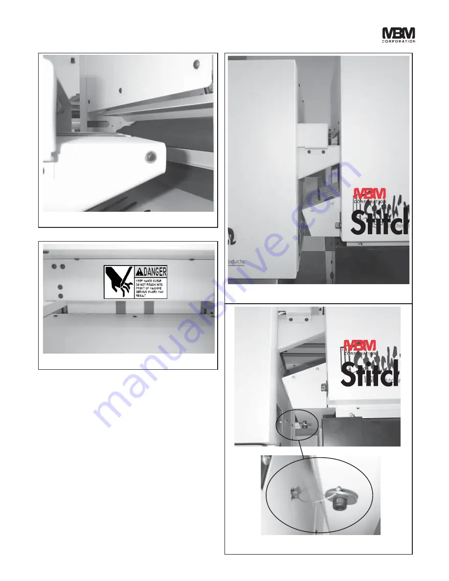
1. Adjust the height of the trimmer so that the top

of the trimmer infeed table is about even with
the middle of the BookletMakers top discharge
roller (see fig 6).

2. Position the trimmer behind the BookletMaker

so that the trimmer's infeed table is centered
with the BookletMakers discharge, and slightly
away from the BookletMaker's top discharge
roller (see figs. 7&8).

3. Install the safety interlock key that is hanging

from the bottom of the back cover (see fig 9).

(Fig 6)

(Fig 7)

(Fig 8)

(Fig 9)

Summary of Contents for StitchFold

Page 1: ...Sales Service Repair Professional Service Fast Nationwide Shipping 1 866 455 9900 www OnlineSkyline com CustomerService onlineskyline com ...

Page 2: ...Trimmer OPERATION MANUAL Trimmer ...

Page 3: ... 5 Installation 6 8 Setup 9 Control Panel 10 Operation 11 12 Maintenance 13 Adjustments 14 Fuses Access 15 Preventive Maintenance 15 Knife Removal Installation 16 19 Clearing A Trimming Jam 19 Knife Care Tips 20 Notes 21 Trouble Shooting 22 25 CONTENTS ...

Page 4: ...mensions Height 27 38 Width 26 42 Length without discharge table 25 90 Length with fully extended discharge table 48 44 Modes Trim or No trim Electrical Standard outlet 115 Volts 60 Hz 6 Amps 1 4 HP Optional 230Vac 50 Hz 3 Amps INTRODUCTION MBM Corporation is proud to introduce another addition to its complete line of equipment for bookletmaking Now you have the ability to trim books in line This ...

Page 5: ...ver H Left Side Cover Blocks access to low volt age connections and mechanisms that can pinch or cut Do not stick your fingers beyond this cover SAFETY GUARDS figs 1 2 1 Make sure electrical power is turned off be fore performing any adjustment or mainte nance 2 Keep hands hair tools and clothing clear of trimming area 3 Become familiar with the moving components of your machine Keep fingers away ...

Page 6: ...5 SAFETY GUARDS A Top Cover B Front Upper Cover D Front Lower Cover H Left Side Cover E Right Side Cover F Rear Upper Cover G Rear Lower Cover C Infeed Table B o t t o m Cover Fig 1 Fig 2 ...

Page 7: ...l assist you in determining the cost of repairs ELECTRICAL POWER The power cord can be plugged into any 115V 60 Hz 1 Phase 15 Amp circuit The machine draws less than 6 amps SAFETY INTERLOCK SYSTEM Connect the safety interlock system as follows 1 Remove the back cover see fig 3 from the Bookletmaker 2 Put the bolt through the washer of the safety key assembly and screw the bolt half way into the ba...

Page 8: ...etMakers top discharge roller see fig 6 2 Position the trimmer behind the BookletMaker so that the trimmer s infeed table is centered with the BookletMakers discharge and slightly away from the BookletMaker s top discharge roller see figs 7 8 3 Install the safety interlock key that is hanging from the bottom of the back cover see fig 9 Fig 6 Fig 7 Fig 8 Fig 9 ...

Page 9: ...8 Trimmer DISCHARGE CONVEYOR TABLE Install discharge conveyor table per illustrations figs 10 11 12 Fig 10 Fig 11 Fig 12 ...

Page 10: ...back stop assembly forward or back DISCHARGE TABLE ROLLERS Set the discharge table rollers forward for small booklets or backward for large booklets To adjust the rollers loosen thumb screws fig 15 move roller brackets to desired location then retighten thumb screws Fig 13 Fig 14 Fig 15 ward to the desired location There is a pointer on the side of the back stop assembly that points to a trim leng...

Page 11: ...ssed The Emergency Stop botton locks in the down off position until manually turned allowing it to pop back up into the power on position Restart machine per B above D Trimming On Off Selector switch chooses mode of operation On for trimming jobs or Off to allow work to pass through without trimming E Knife Change Black rocker cycles the trimming knife up and down as long as it is depressed Fig 17...

Page 12: ...ld the trim end of the work 10 As the knife bar assembly continues down ward the knive begins to cut trim the work 11 The knife bar then begins cycling back up to the top of it s stroke starting position 12 As the knife bar approaches the top of it s stroke it passes the knife bar proximity sen sor The proximity sensor tells the control circuit that the knife bar has reached the top of it s stroke...

Page 13: ... trimmer DANGER NEVER REACH UNDER THE KNIFE SEVERE LACERATIONS OR DISMEMBERMENT COULD RESULT BELT DRIVE The purpose of the BELT DRIVE rotary switch fig 19 is to make sure the work will square up against the back stop to provide a good square cut booklet The 1 setting means that the internal conveyor belts will shut off quickly after the work is sensed allowing time for the work to square up agains...

Page 14: ...NANCE The instructions on the following pages are for the use of trained personnel only Attempting to perform repair and replacement procedures without proper training may cause machine damage or operator injury ...

Page 15: ...ensor move the sensor so that the top of the sensor is even with the top of the knife bar fig 20 5 Reinstall the left cover BACK STOP GATE ADJUSTMENT The function of the back stop gate is to provide a surface for the work to square up against so that the knife will cut the work squarely The back stop gate must be parallel to the bottom knife 1 Run several pieces of work through the trim cycle 2 By...

Page 16: ...se RTM1330F for 230Vac machine B Control Circuit Fuse Fuse protects transformer If this fuse fails none of the 24VDC compo nents will operate Replace with 1 amp fuse RTM1302F for 115Vac machine or 0 5 amp fuse RTM1329F for 230Vac machine LUBRICATION Disconnect electrical power Next remove the front cover and both side covers Use SAE 20 oil to lubricate porous bronze bear ings plastic bearings chai...

Page 17: ...ches to 5 Remove the left and right side covers 6 Remove the four screws and nuts holding the top infeed table s conveyor bracket to the infeed table 7 Carefully lift the right side of the upper infeed conveyor bracket off the infeed table Swing it out and lay it on the infeed table fig 23 NOTE Be sure the round belt does not come off pulleys and be sure the separating finger stays between belts w...

Page 18: ...ely and secure the knife retaining screws 15 Reverse this procedure to install upper knife LOWER KNIFE REMOVAL THE UPPER KNIFE MUST BE REMOVED per steps 1 13 of Upper Knife Removal page 16 17 BEFORE THE LOWER KNIFE IS REMOVED CAUTION Changing knives can be very dan gerous unless safety precautions are observed and extreme care is taken when handling knives Keep handling of unprotected knives to an...

Page 19: ...ive lower knife flat washers and screws but do not fully tighten because the lower knife must be free to move during the next steps of installation adjustments 4 Manually cycle the knife bar similar to step one to the bottom of it s stroke Install and secure the upper knife per upper knife re moval installation procedure page 16 17 5 Push lower knife firmly against the upper knife Turn the lower k...

Page 20: ...g 30 1 6 turn at a time retighten lower knife securing screws and nuts of adjustment screws 11 Perform another test cut and make further ad justments if necessary Lower Knife Adjustment Screws Fig 30 CLEARING A TRIMMING JAM If the maximum capacity of the trimmer is ex ceeded 50 sheets of 20 stock or 0 20 work thickness the trimming knife will stall near the bottom of the trim cycle and not finish ...

Page 21: ...d bound books can all signifi cantly shorten knife blade life Cutting pure paper such as bond paper with no recyled content will cause less wear on the cutting blade In all cases the operator should continually check the quality of the cut to determine when the knife needs to be sharpened Some characteristics that indicate a blade needs sharpening are The knife hesitates or stalls while making a c...

Page 22: ...21 NOTES ...

Page 23: ...l circuit fuse 4 The green light is on but the motor does not run a Depress the Start Reset toggle switch b Check the 6A 115V or 3A 220V motor fuse 1 Depress the Trimming On Off switch to the On position 1 The work does not stop flat against the back stop gate a Check that knife bar begins cycle at top of stroke b Make sure all lower and upper conveyor belts on the infeed table and middle conveyor...

Page 24: ...23 1 Maximum work thickness has been exceeded Call MBM dealer for service 6 Knife stalls near bottom of trim cycle and does not cut through work ...

Page 25: ...h L3 Knife Proximity Sensor L4 Belt Drive Selector Switch L5 Belt Drive Selector Switch L6 Infeed Photosensor L7 Gate Photosensor L8 Start Reset Switch L9 Belt Drive Selector Switch OUTPUTS L10 L20 Red LIGHT APPLICATION L10 Motor Power Relay L13 Jam Light L14 N A L15 N A L16 Discharge Clutch L17 Conveyor Clutch L18 Jam Detector Relay L19 Gate Solenoid L20 Cut Clutch RTM1172A Layout1 ...

Page 26: ...ing lights will light L2 L3 L6 L7 L10 L13 L16 L17 L18 and L20 L3 and L7 will flash on and off simultaneously Starting at position 1 L4 L5 and L9 will be off At position 2 L4 will turn on At position 3 L4 will turn off and L5 will turn on At position 4 both L4 and L5 will be on At position 5 L4 and L5 will be off and L9 will turn on At position 6 L4 and L9 will be on If the lid is returned to the c...

Page 27: ...FORM QF110 5 20 04 3134 Industry Dr N Charleston SC 29418 1 800 223 2508 1 843 552 2700 Fax 1 843 552 2974 www mbmcorp com ...

Reviews:

Related manuals for StitchFold