


6-6
If open, replace the high limit thermo-
stat.
If closed, apply heat. It should open at
about 250°F (121°C). Otherwise, re-
place the high limit thermostat.
•
•
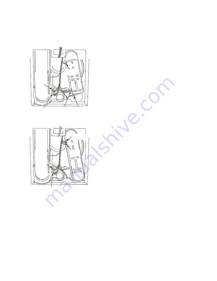
Thermal
Fuse
Thermistor
Thermal
Cut-Off
High Limit
Thermostat
Heat
Element
Thermal Components—Electric
Thermal Cut-Off Test
This unit is equipped with a “one-shot” ther-
mal cut-off. See Thermal Components illus-
trations. If the dryer does not heat with power
supplied:
1. Unplug dryer or disconnect power.
2. Check the thermal cut-off for continuity.
If open, thermal cut-off has failed and
must be replaced.
NOTE:
If the thermal cut-off has failed, replace
the thermal cut-off and high limit thermostat.
In addition, check for failed heat system, or
blocked or improper exhaust system.
Thermal Fuse Test—Electric
A thermal fuse is used on this model. The
thermal fuse is wired in series with the dryer
drive motor. If the thermal fuse opens, power
is shut off to the motor.
1. Unplug dryer or disconnect power.
2. Check continuity of thermal fuse.
3. Once the thermal fuse has opened, it must
be replaced. Check for failed thermistor,
shorted heat element, or other causes of
failure. Replace failed parts. See Ther-
mal Components illustration.
Thermal Fuse Test—Gas
A thermal fuse is used on this model. The
thermal fuse is wired in series with the dryer
gas valve. If the thermal fuse opens, power
is shut off to the motor. (Centrifugal switch in
gas valve also opens heater circuit.)
1. Unplug dryer or disconnect power.
2. Check continuity of thermal fuse.
3. Once the thermal fuse has opened, it
must be replaced. Check for failed therm-
istor or other causes of failure. Replace
failed parts. See Thermal Components
illustration.
•
Thermal
Fuse
Thermistor
High Limit
Thermostat
Thermal Components—Gas
Thermal
Cut-Off


