Maytag MFS 50-125 Installation And Maintenance Instructions Manual Download Page 11

10

INSTALLATION AND MAINTENANCE MANUAL

PUBLICATION DATE 03/02

504 766

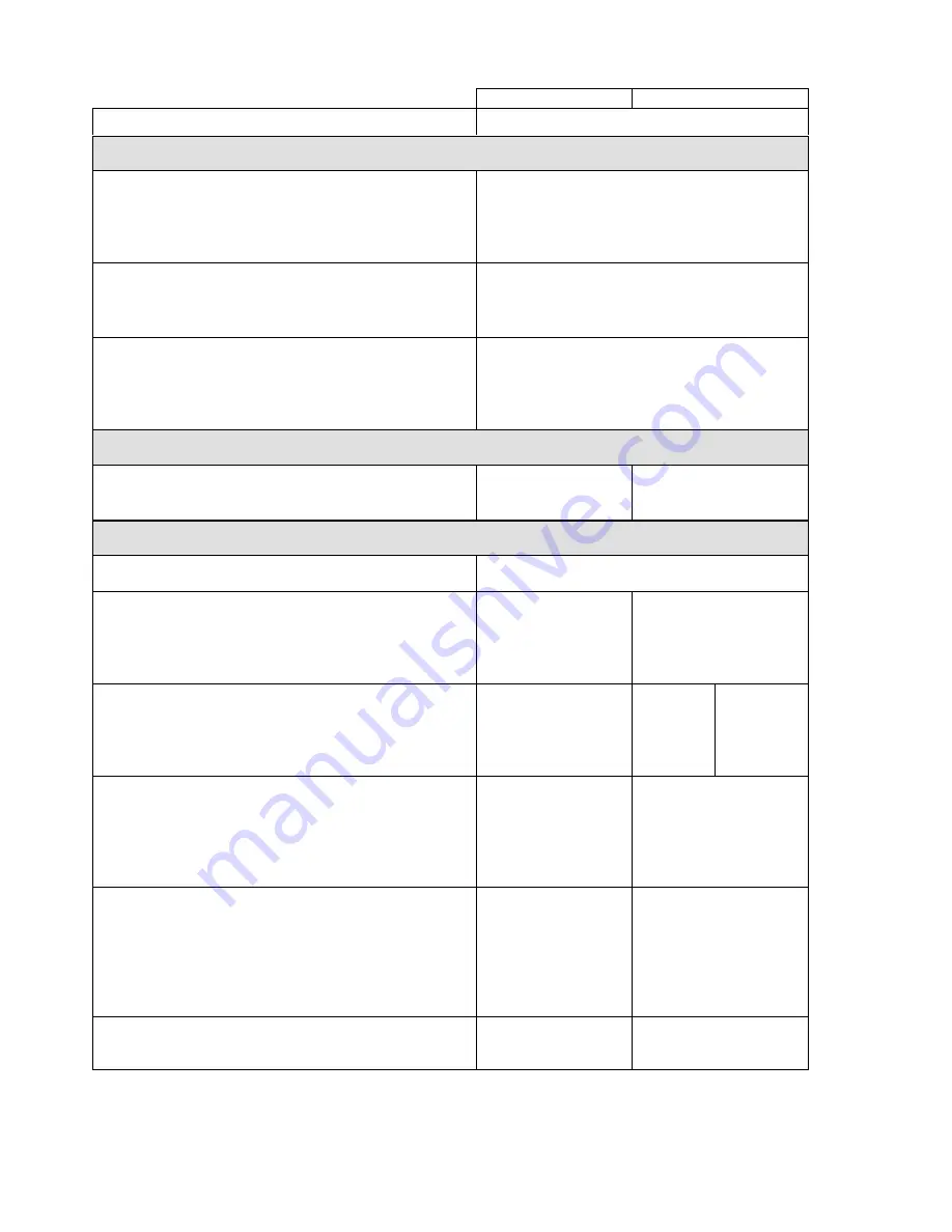
3.4. MACHINES 55kg / 125lbs CAPACITY

 1-Motor version

 2-Motor version

CAPACITY:

 55kg / 125lbs

DIMENSIONS

PACKING DIMENSIONS:

width
depth
height
transportation capacity

1430 mm / 56,3“
1750 mm / 68,9“
2105 mm / 82,87“
 5,3 m

3

 / 187 ft

3

MACHINE DIMENSIONS:

width
depth
height

1195 mm / 47,04“
1610 mm / 63,4“
1905 mm / 75“

DIMENSIONS OF INNER DRUM:

diameter
depth
drum capacity
door opening

914 mm/ 36“
790 mm / 31,1“
518 dm

3

 / 137 gal

540 mm / 21,3“

WEIGHT

WEIGHT:

netto
brutto

1630 kg / 3594 lbs
1770 kg / 3902 lbs

1626 kg / 3585 lbs
1766 kg / 3894 lbs

ELETRICAL DATA

Permitted deviations of feeding voltage for machines:

±10%, with a maximal standard deviation of the
frequency 1%

Electrical system of the machine:

3x380-480V  50/60Hz
3x200-240V  50/60Hz

3x380-415V  50Hz
3x380V  60Hz
3x440-480V  60Hz
3x220-240V  50Hz
3x208-240V  60Hz

TOTAL INPUT OF THE MACHINE WITH:

electric heating 54 kW
no heating
steam heating

62,7 kW
8,7 kW
8,7 kW

380-440V
3AC:

55,8 kW
8,2 kW
8,2 kW

208-240 V /
480V:

56 kW
8,2 kW
8,2 kW

NOMINAL OUTPUT OF THE MOTOR AT RPM:

washing / distribution

spinning low / high

7,5 kW

7,5 kW

400 V: 1,2 / 1,1 kW
230/480V: 1,4/ 1,2kW
400 V: 5,8 / 4,5 kW
230V: 6,5 / 5 kW
480V: 6,5 / 5,5 kW

INPUT PROTECTION FOR ONE MACHINE:

with electric heating 54 kW (3x230V/60Hz)
with electric heating 54 kW (3x400V/50Hz)
without electric heating (3x400V/ 50 Hz, 3x480 V/ 60 Hz)
with steam heating (3x230 V/60 Hz)
without electric heating (3x230 V / 60 Hz)
with steam heating (3x400 V/50 Hz)

160 A
100 A
32 A
40 A
40 A
32 A

160 A
100 A
25 A
30 A
30 A
25 A

Overload protection of the motor:

eletronic protection
on the frequency
invertor

overcurrent relay

tab. 3.4

*

Summary of Contents for MFS 50-125

Page 1: ...MFS 50 125 INSTALLATIONANDMAINTENANCEINSTRUCTIONS INDUSTRIALWASHER PUBDATE 03 02 EXTRACTORS 504766...

Page 2: ...5 PUTTING THE MACHINE INTO SERVICE 23 5 MAINTENANCE 24 5 1 INTRODUCTION 24 5 2 DAILY 24 5 3 MONTHLY OR AFTER 200 WORKING HOURS 24 5 4 EVERY 3 MONTHS OR AFTER 500 WORKING HOURS 24 5 5 EVERY 6 MONTHS O...

Page 3: ...machine with frequency inverter do not change the parameters of the inverter Doing so can cause serious injury fire machine damage etc Instructions and warnings included in this manual do not cover al...

Page 4: ...uses any responsibilities in such cases Define dangerous areas in the laundry room and do not allow people to enter if the machine is in operation MACHINE INFORMATION This manual comprises information...

Page 5: ...mal standard deviation of the frequency 1 Electrical system of the machine 3x380 415V N 50 60Hz applicable for el heating 1x220 240V 50 60Hz not applicable for el heating 3x220 240V 50 60Hz applicable...

Page 6: ...y system 1 connection for manifold 1 5 6 10 connections to liquid soap supply system Soap hoppers 3 5 5 CONSUMPTION Mean water consumption depends on selected programme cca 550 dm3 145 US gal STEAM CO...

Page 7: ...imal standard deviation of the frequency 1 Electrical system of the machine 3x380 480V 50 60Hz 3x200 240V 50 60Hz 3x380 415V 50Hz 3x380V 60Hz 3x440 480V 60Hz 3x220 240V 50Hz 3x208 240V 60Hz TOTAL INPU...

Page 8: ...or manifold 1 5 6 10 connections to liquid soap supply system Soap hoppers 5 CONSUMPTION Mean water consumption depends on selected programme cca 900 dm 3 240 US gal STEAM CONSUMPTION depends on selec...

Page 9: ...mal standard deviation of the frequency 1 Electrical system of the machine 3x380 480V 50 60Hz 3x200 240V 50 60Hz 3x380 415V 50Hz 3x380V 60Hz 3x440 480V 60Hz 3x220 240V 50Hz 3x208 240V 60Hz TOTAL INPUT...

Page 10: ...for manifold 1 5 6 10 connections toliquid soap supply system Soap hoppers 5 CONSUMPTION Mean water consumption depends on selected programme cca 1195 dm3 315 US gal STEAM CONSUMPTION depends on sele...

Page 11: ...em of the machine 3x380 480V 50 60Hz 3x200 240V 50 60Hz 3x380 415V 50Hz 3x380V 60Hz 3x440 480V 60Hz 3x220 240V 50Hz 3x208 240V 60Hz TOTAL INPUT OF THE MACHINE WITH electric heating 54 kW no heating st...

Page 12: ...r manifold 1 5 6 10 connections to liquid soap supply system Soap hoppers 5 CONSUMPTION Mean water consumption depends on selected programme cca 1500 dm3 400 US gal STEAM CONSUMPTION depends on select...

Page 13: ...INSTALLATION AND MAINTENANCE MANUAL PUBLICATION DATE 03 02 504 766 3 5 DIMENSIONS AND CONNECTIONS OF THE MACHINE 33 40 55 kg 80 100 125 lbs 22 kg 50 lbs 5 soaphoppers 22 kg 50 lbs 3 soaphoppers Fig 3...

Page 14: ...50 mm 1 97 50 mm 1 97 50 mm 1 97 H 1233 mm 48 54 two motors 1437 mm 56 57 one motor 1233 mm 48 54 1617 mm 63 66 1617 mm 63 66 1617 mm 63 66 I 173 mm 6 79 J 401 mm 15 8 two motors 87 mm 3 43 one motor...

Page 15: ...city M12 To remove the machine to its final location follow these precautions All passages and spaces the machine has to be transported through at installation should be reasonably dimensioned to meet...

Page 16: ...END TO INSTALL THE WASHING MACHINE IN A ROOM WITH A CELLAR OR ON A FLOOR HAVING ROOMS BENEATH WARNING IN CASE OF INSTALLATION IN A ROOM WITH A CELLAR OR ON A FLOOR HAVING ROOMS BENEATH THE INSTALLATIO...

Page 17: ...BOLT M10 x 160 mm M16 x 160 mm TIGHTENING MOMENT 49 Nm 36 lbf ft 210 Nm 155 lbf ft Tab 4 3 B Fig 4 3 A Distances between washing machines walls and between other machines and optional design of the wa...

Page 18: ...ould be made to make the water softer Only in some cases is the use of hard water desirable such as adding softener in the linen The soap supplier can help you with making the right decisions concerni...

Page 19: ...for connecting to the laundry steam line For dimensions of connection points see fig 3 5 The value of inlet steam pressure must correspond to the range stated in chapter 2 Technical specification Any...

Page 20: ...OT BE SUITABLE FOR CONNECTING TO AN IT SUPPLY SYSTEM 1 Earth leakage trip 2 Laundry electrical switchboard 3 Power supply protection 4 Washing machine 5 Phase conductors 6 Protective conductor 7 Main...

Page 21: ...termined for strong electric circuits i e motors heating elements motor contactors circuit breaker main switch etc see the inner connecting diagram list A supplied with the machine SUPPLY CABLE CONNEC...

Page 22: ...FRONT VIEW IN COUNTERCLOCKWISE DIRECTION DURING EXTRACTION IF IT ROTATES IN OPPOSITE DIRECTION DISCONNECT TWO PHASES SWITCH THEM OVER AND CHECK AGAIN THE ROTATION DIRECTION 1 Main switch 2 Bushing 3 C...

Page 23: ...machine water system Fig 4 4 E CHECK IF THE HOSE IS TIGHTEN BY CLAMP ANY LEAKAGE OF CHEMICALS MAY CAUSE THE PARTS CORROSION INSIDE OF THE MACHINE WARNING PLACE EXTERNAL MIXER MIXERS NEAR THE MACHINE...

Page 24: ...into service remove the three striking colour transport braces securing the vibrating machine components during the transport One brace fig 3 11 A B pos 1 is located in the front part of the machine a...

Page 25: ...f washing soaps 4 Soap hoppers must be cleaned at the end of each working day 5 Clean up the door gaskets to remove sediments and dirt Do not use solvents or acids to clean the rubber door gasket Do n...

Page 26: ...to the rubber bushing 3 located into the limiter 2 which is bolted to the drum front face 1 The switch attached to the switchboard is a part of the machine skeleton which is attached to the frame and...

Page 27: ...y is to order the original part according the Spare parts manual WARNING REPLACE THE DAMAGED BOLT WITH A ONE OF THE SAME STRENGTH VALUE MARKED ON ITS HEAD IGNORING OF THE BOLT QUALITY AND MECHANICAL S...

Page 28: ...Bolt nut Dimension Number of pcs Tightening Moments Nm Tightening Moments lbf ft A M20 x 65 24 12 600 00 443 00 B M12 x 30 8 70 00 52 00 33 kg TYPE nut KM13 1 450 00 332 00 C M12 x 35 6 70 00 52 00 D...

Page 29: ...ricator Fig 5 8 Lubrication places of 33 40 55 kg 80 100 125 lbs machine for bearing house placed on rear of machine FOR ALL MACHINES 22 55 kg 50 125 lbs Once in 6 months or when needed grease spring...

Page 30: ...it on the pulley faces If all points A B C D are touching the ruler the pulleys are aligned 1 Main housing with the pulley 2 Drum 3 Drive motor 4 Ruler Fig 5 9 5 10 WATER AND STEAM FILTERS Machines a...

Page 31: ...usted tighten up the securing bolt 1 to the groove in the casing 2 thread Fig 5 11 A Machines 22 kg 50 lbs 1 Handle bolt 2 Handle sleeve 3 Door carrier beam 4 Semicircle cuts 5 Handle pin 6 Hinge bolt...

Page 32: ...e has overload motor current protection by overcurrent relay All current protections have been set to the value according to a machine type stated on the power electrical scheme delivered with machine...

Page 33: ...TRIPS If the laundry is equipped with the earth leakage trip in the inlet circuit of the electric switchboard it is necessary to test it regularly The earth leakage trip is a very sensitive device an...

Page 34: ...uation occurs when microprocessor version at the end of a programme or when pressing the Stop button and the following function described in the Programming manual Electronic programmer card version W...

Page 35: ...e inlet valve change the valve Water escaping check the inlet pipeline hoses valves filters tapes clamps their connections and eliminate possible leakage 6 3 TOO LONG HEATING TIME Electrical heating e...

Page 36: ...ed drainage valve clean the drainage valve or exchange it Too small waste sump dimensions check the waste sump diameters and enlarge it accordingly 6 5 PROGRAMMER PROBLEMS See the chapter Troubleshoot...

Page 37: ...witch 83 161 3 modification 1 F02 117 002 224 Microswitch 83 161 3 modification 2 PRI 401 020 021 Fuse 1 6 A 345 805 363 032 Fuse 2 5 A 345 805 163 032 Fuse 1A F02 117 001 814 Coil modification F02 10...

Page 38: ...163 032 Fuse 1A 100 521 Grey keyboard MCB FC 100 629 Black keyboard MCB FC PRI 340 015 019 Thermostat sensor 22 kg 50 lbs 100 052 Black keyboard MCB EC PRI 348 000 123 Grey keyboard MCB EC 503 839 Th...

Page 39: ...the machine will never be used again dismantle carefully the door with the hinge chapter 5 12 BE CAREFUL FALLING DOOR AND GLASS CAN CAUSE INJURIES 8 2 MACHINE LIQUIDATION For the machine liquidation a...

Page 40: ...CARD PROGRAMMER K24 INSTALLATION DATE INSTALLATION CARRIED OUT BY SERIAL NUMBER ELECTRICAL DETAILS VOLT PHASE HZ NOTE ANY CONTACTS WITH YOUR DEALER REGARDING MACHINE SAFETY OR SPARE PARTS MUST INCLUD...

Reviews: