Maytag MDG76PC Installation Manual Download Page 21

17

IMPORTANT:

Exhaust back pressure measured by a manometer in the exhaust duct 

must be

 no less

than 0 and 

must not exceed 

0.3 inches (0.74 mb) of water column.

IMPORTANT:

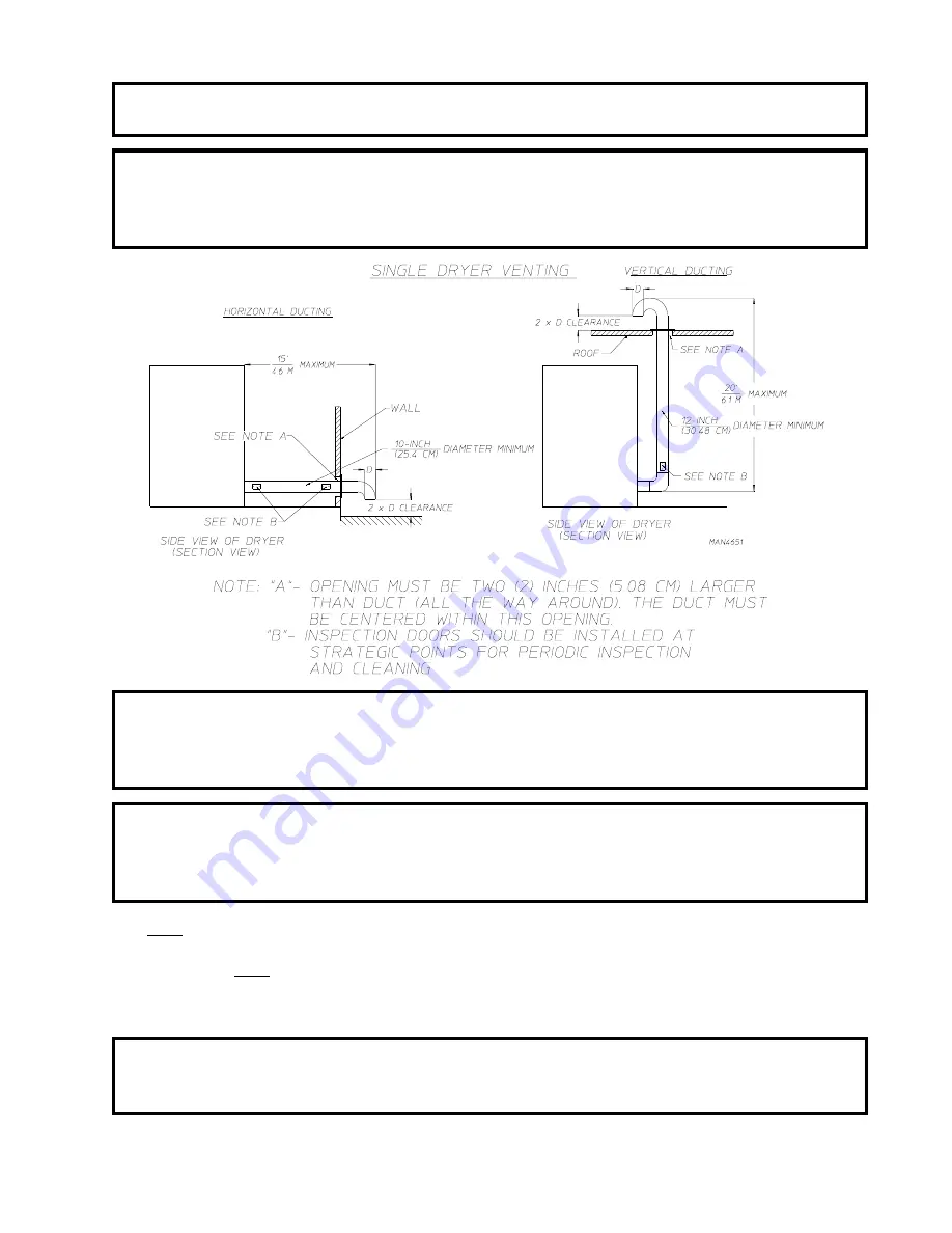
Minimum duct size for a dryer that is vented vertically is 12-inches (30.48 cm) for a
round duct or an equivalent of 80 square inches (516.1 square centimeters).  

THE

DUCT SIZE MUST NOT BE REDUCED ANYWHERE DOWNSTREAM OF
THE DRYER.

IMPORTANT:

For extended ductwork runs, the cross section area of the ductwork can only be
increased to an extent.  When the ductwork approaches the maximum limits noted in
this manual, a professional heating, venting, and air conditioning (HVAC) firm 

should

be

 consulted for proper venting information.

NOTE:

As per the National Fuel Gas Code, “Exhaust ducts for type 2 clothes dryers shall be
constructed of sheet metal or other noncombustible material.  Such ducts shall be equivalent in
strength and corrosion resistance to ducts made of galvanized sheet steel not less than
0.0195-inches (26 gauge [0.05 mm]) thick.”

ALL

 ductwork 

should be

 smooth inside with no projections from sheet metal screws or other obstructions,

which will collect lint.  When adding ducts, the duct to be added should overlap the duct to which it is to be
connected.  

ALL

 ductwork joints 

must be

 taped to prevent moisture and lint from escaping into the

building.  Inspection doors 

should be

 installed at strategic points in the exhaust ductwork for periodic

inspection and cleaning of lint from the ductwork.

NOTE:

When the exhaust ductwork passes through a wall, ceiling, or roof made of combustible
materials, the opening 

must be

 2-inches (5.08 cm) larger than the duct (all the way around).

The duct 

must be

 centered within this opening.

Summary of Contents for MDG76PC

Page 1: ...pplier AVERTISSEMENT Assurez vous de bien suivrelesinstructionsdonn esdanscettenotice pour r duire au minimum le risque d incendie ou d explosion ou pour viter tout dommage mat riel touteblessureoulam...

Page 2: ...the dryer The following FOR YOUR SAFETY caution must be posted near the dryer in a prominent location We have tried to make this manual as complete as possible and hope you will find it useful The man...

Page 3: ...ERATION CAUTION DRYERSSHOULDNEVERBELEFTUNATTENDEDWHILEINOPERATION FORYOUR SAFETY DONOTDRYMOPHEADSINTHEDRYER DONOTUSEDRYERINTHEPRESENCEOFDRYCLEANINGFUMES WARNING UNDER NO CIRCUMSTANCES should the dryer...

Page 4: ...included with the dryer Dryer must not be installed or stored in an area where it will be exposed to water or weather The wiring diagram for the dryer is located in the front electrical control box ar...

Page 5: ...S 10 A LocationRequirements 10 B Unpacking SettingUp 11 C DryerEnclosureRequirements 13 D FreshAirSupplyRequirements 14 E ExhaustRequirements 15 F ElectricalInformation 19 G GasInformation 23 H Prepar...

Page 6: ...SECTION V DATA LABEL INFORMATION 33 A Data Label 33 SECTION VI PROCEDURE FOR FUNCTIONAL CHECK OF REPLACEMENT COMPONENTS 35...

Page 7: ...not damaged in a damaged shipment should be accepted but the number received and the number refused must be noted on the receipt 4 If you determine that the dryer was damaged after the trucker has le...

Page 8: ...ll your gas supplier from a neighbor s phone Follow the gas supplier s instructions f If you cannot reach your gas supplier call the fire department 4 Installation and service must be performed by a q...

Page 9: ...RNING PERSONALINJURY OR FIRE COULD RESULT 10 This dryer is not to be used in the presence of dry cleaning solvents or fumes 11 Remove articles from the dryer as soon as the drying cycle has been compl...

Page 10: ...vestherighttomakechangesinspecificationsatanytimewithoutnoticeor obligation 052103 BASKET TUMBLER DIAMETER 44 1 2 113 03 cm BASKET TUMBLER DEPTH 24 7 8 63 18 cm BASKET TUMBLER MOTOR 1 hp 0 746 kW DOOR...

Page 11: ...7 Specifications MDG76PC NOTE Manufacturerreservestherighttomakechangesinspecificationsatanytimewithoutnoticeor obligation...

Page 12: ...llus No Description 1 Controls 2 Control top access Door Assembly 3 Main DoorAssembly 4 Lint Compartment Area lint screen located behind door 5 Data Label and Installation Label affixed to the left si...

Page 13: ...tric Service Relay Box 3 Basket tumbler Bearing Mount Assembly 4 Idler Bearing MountAssembly 5 Basket tumbler drive Motor Assembly for reversing models ONLY 6 Blower Motor Assembly 7 Dryer Exhaust Ele...

Page 14: ...Installation and Gas Plumbing 1 The dryer must be installed on a sound level floor capable of supporting its weight Carpeting must be removed from the floor area that the dryer is to rest on IMPORTANT...

Page 15: ...he four 4 bolts securing the base of the dryer to the wooden skid Two 2 are at the rear base remove the back panel for access and two 2 are located in the bottom of the lint chamber To remove the two...

Page 16: ...to the top of the dryer shown in the illustration below d Remove the two 2 self taping screws on the back electrical box and pull through ALL associated wires from the motor to this electrical box ref...

Page 17: ...m allowance must be made for the opening and closing of the control door and the lint door It is suggested that the dryer be positioned about 2 feet 0 61 meters away from the nearest obstruction for e...

Page 18: ...s for adequate combustion and make up air supply To compensate for the use of registers or louvers used over the openings this make up air must be increased by approximately thirty three percent 33 Ma...

Page 19: ...eter of the duct Including basket tumbler dryer elbow connections or elbows used for outside protection from the weather no more than two 2 elbows should be used in the exhaust duct run If more than t...

Page 20: ...ow bent downward should be installed where the exhaust exits the building If the ductwork travels vertically up through the roof it should be protected from the weather by using a 180 turn to point th...

Page 21: ...for type 2 clothes dryers shall be constructedofsheetmetalorothernoncombustiblematerial Suchductsshallbeequivalentin strength and corrosion resistance to ducts made of galvanized sheet steel not less...

Page 22: ...exits the building If the ductwork travels vertically up through the roof it should be protected from the weather by using a 180 turn to point the opening downward In either case allow at least twice...

Page 23: ...Codes Parts 1 2 CSAC22 1 1990 or LATEST EDITION IMPORTANT Failure to comply with these codes or ordinances and or the requirements stipulated inthismanualcanresultinpersonalinjuryorcomponentfailure N...

Page 24: ...NOTES A B When fuses are used they must be dual element time delay current limiting class RK1 or RK5 ONLY Calculate determine correct fuse value by applying either local and or National Electrical Cod...

Page 25: ...ere are any nonmetallic interruptions such as a meter pump plastic rubber or other insulating connectors they must be jumped out with no 4 copper wire and securely clamped to bare metal at both ends I...

Page 26: ...e the wiring enters the dryer NOTE ACIRCUIT SERVICINGEACH DRYER MUST BE PROVIDED If local codes permit power to a gas dryer can be made by the use of a flexible U L listed power cord pigtail wire size...

Page 27: ...WARNING FIRE OR EXPLOSION COULD RESULT 1 Gas Supply The gas dryer installation must meet the American National Standard National Fuel Gas Code ANSI Z223 1 LATESTEDITION or in Canada the Canadian Insta...

Page 28: ...each gas valve pressure tap must be a consistent 10 5 inches 26 1 mb water column There is no regulator or regulation provided in an L P dryer The water column pressure must be regulated at the source...

Page 29: ...T inlet pipe connection located at the right side of the base of the dryer The minimum pipe size supply line to the dryer is 3 4 N P T For ease in servicing the gas supply line of each dryer must hav...

Page 30: ...detergentworkswell WARNING NEVER TEST FOR LEAKSWITHAFLAME ALL components materials must conform to National Fuel Gas Code SpecificationsANSI Z223 1 LATEST EDITION or in Canada CAN CGA B149 1 M91 Natur...

Page 31: ...LS the sail switch damper assembly was installed and adjusted at the factory prior to shipping However each sail switch adjustment must be checked to assure that this important safety control is funct...

Page 32: ...atALL gas shutoff valves are open NOTE Gas dryers are equipped with a Direct Spark Ignition DSI system which has internal diagnostics Ifignitionisnotestablishedwithinthree 3 times theheatcircuitintheD...

Page 33: ...er should be operated through one 1 complete cycle to assure that no further adjustments are necessary and that ALL components are functioning properly BASKET TUMBLER COATING The basket tumbler is tre...

Page 34: ...d time has expired NOTE To stop dryer open main door Continuation of the cycle will resume only after the door has been closed and any of the three 3 temperature selection is pressed 5 Upon completion...

Page 35: ...BLE VAPORS AND LIQUIDS NOTE Suggested time intervals shown are for average usage which is considered six 6 to eight 8 operational running hoursperday IMPORTANT Dryer produces combustible lint and must...

Page 36: ...aningofappliancesisrecommended B ADJUSTMENTS 7 DAYS AFTER INSTALLATION AND EVERY 6 MONTHS THEREAFTER Inspect bolts nuts screws bearing setscrews grounding connections and nonpermanent gas connections...

Page 37: ...er or the Maytag Co certain information is required to insure proper service parts information This information is on the data label affixed to the left side panel area behind the top control access d...

Page 38: ...ions on your particular model 4 TYPE OF HEAT This describes the type of heat for your particular dryer gas either natural gas or liquid propane L P gas or steam 5 HEAT INPUT for GAS DRYERS This descri...

Page 39: ...1 Upon completing installation of the replacement microprocessor controller computer board reestablish power to the dryer 2 Start the drying cycle by pressing any temperature selection keys HI LO PP...

Page 40: ...at The DSI module will LOCKOUT if the gas burner flame is not sensed at the end of the trial for ignition period The trial for ignition period will be repeated for a total of three 3 retries trials th...

Page 41: ...Part No 113184 1 04 23 03 25 2 05 14 03 25 3 05 27 03 CODEB...

Reviews: