Maytag MDG50MNV Installation Manual Download Page 36

32

SECTION VII

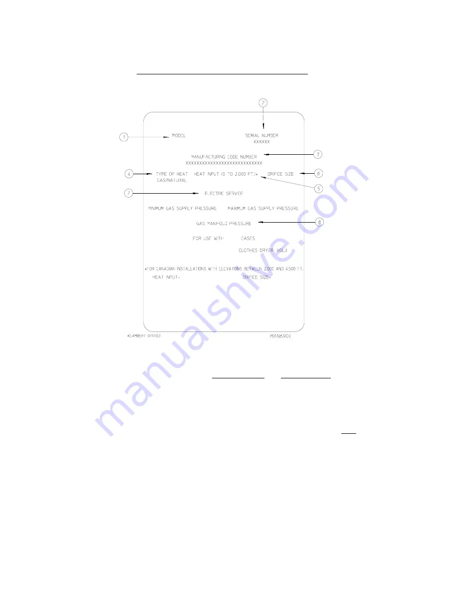
DATA LABEL INFORMATION

When contacting the

 Maytag Co

., certain information is required to ensure proper service/parts information.

This information is on the data label affixed to the left side panel area behind the top control (access) door.
When contacting the

 Maytag Co.

, please have the 

model number

 and 

serial number

 available.

1.

MODEL NUMBER

 – Describes the size of the dryer and the type of heat (gas, electric, or steam).

2.

SERIAL NUMBER

 – Allows the manufacturer to gather information on your particular dryer.

3.

MANUFACTURING CODE NUMBER

 – The number issued by the manufacturer

,

 which describes 

ALL

 possible options

on your particular model.

4.

TYPE OF HEAT

 – This describes the type of heat for your particular dryer, gas (either natural gas or liquid propane [L.P.]

gas), electric, or steam.

5.

HEAT INPUT 

(for GAS DRYERS) – This describes the heat input in British Thermal Units per Hour (Btu/hr).

6.

ORIFICE SIZE 

(for GAS DRYERS) – Gives the number drill size used.

7.

ELECTRIC SERVICE

 – This describes the electric service for your particular model.

8.

GAS MANIFOLD PRESSURE 

(for GAS DRYERS) – This describes the manifold pressure taken at the gas valve tap.

Summary of Contents for MDG50MNV

Page 1: ...oisin Suivez les instructions du fournisseur Si vous ne pouvez rejoindre le fournisseur de gaz appelez le service des incendies L installation et l entretien doivent être assurés par un installateur ou un service d entretien qualifié ou par le fournisseur de gaz WARNING For your safety the information in this manual must be followed to minimize the risk of fire or explosion and to prevent property...

Page 2: ...ications colors and material and to change or discontinue models The illustrations included in this manual may not depict your particular dryer exactly Important For your convenience log the following information DATE OFPURCHASE ____________________________________________________ MODEL NO ______________________ DEALER SNAME _________________________________________________________________________...

Page 3: ...TESTING OF ANY EQUIPMENT PER OSHA Occupational Safety and Health Administration STANDARDS Caution Label all wires prior to disconnection when servicing controls Wiring errors can cause improper operation Attention Au moment de l entretien des commandes étiquetez tous les fils avant de les débrancher Des erreurs de câblage peuvent entraîner un fonctionnement inadéquat et dangereux State of Californ...

Page 4: ...ITHOUTTHE LINTFILTER SCREEN IN PLACE EVENIFANEXTERNALLINTCOLLECTIONSYSTEMISUSED Dryer must not be installed or stored in an area where it will be exposed to water or weather The wiring diagram for the dryer is located in the front electrical control box area IMPORTANT Dryer must be installed in a location environment which the ambient temperature remains between 40 F 4 44 C and 130 F 54 44 C WARNI...

Page 5: ...austRequirements 11 F ElectricalInformation 16 G GasInformation 19 H Preparation For Operation Start Up 23 I PreoperationalTests 24 J PreoperationalInstructions 25 K ShutdownInstructions 26 SECTION IV SERVICE PARTS INFORMATION 27 A Service 27 B Parts 27 SECTION V WARRANTY INFORMATION 28 A ReturningWarrantyCards 28 B Warranty 28 SECTION VI ROUTINE MAINTENANCE 29 A Cleaning 29 B Adjustments 30 C Lub...

Page 6: ...MATION 32 SECTION VIII PROCEDURE FOR FUNCTIONAL CHECK OF REPLACEMENT COMPONENTS 33 SECTION IX MANUAL RESET BURNER HI LIMIT INSTRUCTIONS 36 A Phase 7 36 B DualTimer 36 SECTION X SENSOR ACTIVATED FIRE EXTINGUISHING S A F E SYSTEM 37 ...

Page 7: ...ch c DO NOT use any phone in your building d Clear the room building or area of ALL occupants e Immediately call your gas supplier from a neighbor s phone Follow the gas supplier s instructions f If you cannot reach your gas supplier call the fire department 4 Installation and service must be performed by a qualified installer service agency or gas supplier 5 Dryers must be exhausted to the outdoo...

Page 8: ...yer door switch lint drawer switch or heat safety circuit ever be disabled WARNING PERSONALINJURYOR FIRE COULD RESULT SHOULD THE DRYER DOOR SWITCH LINT DRAWER SWITCH OR HEAT SAFETYCIRCUIT EVER BE DISABLED 10 This dryer is not to be used in the presence of dry cleaning solvents or fumes 11 Remove articles from the dryer as soon as the drying cycle has been completed WARNING Articlesleftinthedryeraf...

Page 9: ... BASKET TUMBLER DEPTH 37 1 2 95 3 cm BASKET TUMBLER MOTOR 3 4 hp 0 560 kW DOOR OPENING DIAMETER 21 1 2 54 61 cm BASKET TUMBLER VOLUME 18 3 cu ft 0 518 cu m DRYERS PER 20 40 CONTAINER 10 20 DRYERS PER 45 48 TRUCK 24 26 WATER CONNECTION 3 4 11 5 NH VOLTAGE AVAILABLE 120v 1ø 2w 60 Hz APPROX WEIGHT UNCRATED 651 lbs 295 3 kg APPROX WEIGHT CRATED 700 lbs 317 7 kg HEAT INPUT 150 000 Btu hr 37 800 kcal hr...

Page 10: ...6 NOTE Manufacturerreservestherighttomakechangesinspecificationsatanytimewithoutnoticeor obligation Specifications ...

Page 11: ...yer IMPORTANT Dryer must be transported and handled in an upright position at ALLtimes The dryer can be moved to its final location while still attached to the skid or with the skid removed To unskid the dryer locate and remove the four 4 bolts securing the base of the dryer to the wooden skid Two 2 are at the rear base remove the back panel for access and two 2 are located in the bottom of the li...

Page 12: ...sh Air Supply Requirements in Section D 5 Clearance provisions must be made from combustible construction as noted in this manual refer to Dryer Enclosure Requirements in Section C 6 Provisions must be made for adequate clearances for servicing and for operation as noted in this manual refer to Dryer Enclosure Requirements in Section C 7 The dryer must be installed with a proper exhaust duct conne...

Page 13: ...s required providing no sprinkler is located above the dryer For steam dryers or if a sprinkler is located above the dryer 18 inches 45 72 cm is required D Dryer should be positioned 12 inches 30 48 cm away from the nearest obstruction and 24 inches 60 96 cm is recommended for ease of installation maintenance and service E 2 inch 5 08 cm minimum is required for opening the control door F Flooring ...

Page 14: ...tributed equally to the dryers The dryer must be installed with provisions for adequate combustion and make up air supply EXAMPLE For a bank of eight 8 dryers two 2 unrestricted openings measuring 3 feet by 2 feet 0 914 meters by 0 61 meters are acceptable IMPORTANT Make up air openings should not be located in an area directly near where exhaust ventsexitthebuilding Allowances must be made for re...

Page 15: ...t to which it is connected ALL ductwork joints must be taped to prevent moisture and lint from escaping into the building Additionally inspection doors should be installed at strategic points in the exhaust ductwork for periodic inspection and cleaning IMPORTANT When connecting ductwork to the dryer exhaust duct be sure that when screws are used they DO NOT restrict the operation both opening and ...

Page 16: ... over 20 feet 6 1 meters a minimum size of 10 inches 25 4 cm must be used HORIZONTAL VENTING When a single 8 inch 20 32 cm horizontal vent is used the ductwork to the outlet cannot exceed 20 feet 6 1 meters refer to Illus A below This calculation of 20 feet 6 1 meters compensates or allows for the use of a maximum of only one 1 elbow which is the outside outlet protection Illus A IMPORTANT Exhaust...

Page 17: ...f elbows used exceeds the above noted specifications the cross sectional area of the ductwork must be increased in proportion to the number of elbows or duct run added IMPORTANT For extended ductwork runs the cross section area of the duct can only be increased to an extent For extended ductwork runs a professional heating ventilating and air conditioning HVAC firmshouldbeconsultedforproperventing...

Page 18: ...ts being connected to the main common ductmust be a minimumof34 1 4 87cm dryerwidth Ductwork should be laid out in such a manner where allowances are made at rear area of the dryer for removal of rear service panels or guards The illustrations on page 15 show the minimum cross section area for multiple dryer venting These figures must be increased in proportion if the main duct run from the last d...

Page 19: ...15 HORIZONTAL VENTING Illus C VERTICAL VENTING Illus D ...

Page 20: ... protected branch circuit The dryer must be connected with copper wire only DO NOT use aluminum wire which could cause a fire hazard The copper conductor wire cable must be of proper ampacity and insulation in accordance with electric codes for making ALL service connections NOTE TheuseofaluminumwirewillVOIDTHEWARRANTY IMPORTANT Aseparate protected circuit must be provided to each dryer NOTE An in...

Page 21: ...ipe The grounded cold water pipe must have metal to metal connection ALL the way to the electrical ground If there are any nonmetallic interruptions such as a meter pump plastic rubber or other insulating connectors they must be jumped out with no 4 copper wire and securely clamped to bare metal at both ends IMPORTANT For personal safety and proper operation the dryer must be grounded Provisions a...

Page 22: ...ses a strain relief must be installed where the wiring enters the dryer IMPORTANT Aseparate protected circuit must be provided to each dryer Single Phase 1ø Wiring Connections Hookup The electrical input connections on ALL single phase 1ø gas dryers are made into the rear service box located at the upper left area of the dryer A ground lug is provided in the rear electrical box to connect your ser...

Page 23: ...an cause irreparable damage to the gas valve which willVOIDTHEWARRANTY WARNING FIRE OR EXPLOSION COULD RESULT DUE TO FAILURE OF ISOLATINGOR DISCONNECTINGTHE GAS SUPPLYAS NOTED 1 Gas Supply The gas dryer installation must meet the American National Standard National Fuel Gas Code ANSI Z223 1 LATESTEDITION or in Canada the Canadian Installation Codes CAN CGA B149 1 M91 Natural Gas or CAN CGA B149 2 ...

Page 24: ... the gas pressure must be regulated upstream of the dryer The pressure measured at each gas valve pressure tap must be a consistent 10 5 inches 26 1 mb water column There is no regulator or regulation provided in an L P dryer The pressure must be regulated at the source L P tank or an external regulator must be added to each dryer Shaded area is stated in metric equivalent Drill Measurement Size D...

Page 25: ...liance Btus being supplied The dryer is provided with a 1 2 N P T inlet pipe connection extending out the back area of the burner box The minimum pipe size supply line to the dryer is 1 2 diameter For ease in servicing the gas supply line of each dryer must have its own shutoff valve The size of the main gas supply line header will vary depending on the distance this line travels from the gas mete...

Page 26: ...r and safe operation A 1 8 N P T plugged tap accessible for a test gauge connection must be installed in the main gas supply line immediately upstream of each dryer IMPORTANT Pipe joint compounds that resist the action of natural gas and L P gas must be used IMPORTANT TestALLconnectionsforleaksbybrushingonasoapywatersolution liquid detergentworkswell WARNING NEVER TEST FOR LEAKSWITHAFLAME IMPORTAN...

Page 27: ...sted at the factory prior to shipping However each sail switch adjustment must be checked to ensure that this important safety control is functioning 5 Check bolts nuts screws terminals and fittings for tightness and security 6 GAS MODELS be sure that ALL gas shutoff valves are in the open position 7 Check that ALL back guard panels and service box covers have been replaced 8 Check the lint drawer...

Page 28: ...e ignitions total of three 3 ignition attempts If there is no flame after the third ignitionattemptthemodulewilllockoutuntilitismanuallyreset Toresettheignitionsystem open and close the main door and restart the dryer b A gas pressure test should be taken at the gas valve pressure tap of each dryer to ensure that the water column W C pressure is correct and consistent NOTE Water column pressure re...

Page 29: ...Y meaning no cycle in progress 2 Press the letter on the keyboard touch pad corresponding to the cycle desired i e key E to start rotate the dryer 3 L E D display will now show Cycle In Progress and Cycle Status meaning that the dryer is in the drying cycle dry mode for 30 minutes and count downwards in minutes NOTE Pressing keyboard touch pad key A B C D or F will also start the dryer The six 6 p...

Page 30: ...ocated on the electronic timer as noted in the illustration below K SHUTDOWN INSTRUCTIONS If the dryer is to be shutdown taken out of service for a period of time the following must be performed 1 Discontinue power to the dryer either at the external disconnect switch or the circuit breaker 2 Discontinue the heat supply GAS MODELS discontinue the gas supply a SHUT OFF external gas supply shutoff v...

Page 31: ...tacting the Maytag Co be sure to give them the correct model number and serialnumbersothatyourinquiryishandledinanexpeditiousmanner B PARTS Replacement parts should be purchased from the dealer from whom the Maytag equipment was purchased If the dealer cannot be contacted or is unknown contact the Maytag Co for a dealer in your area NOTE When ordering replacement parts from the Maytag dealer or th...

Page 32: ...mpleted and returned for each individual dryer NOTE Besuretoincludetheinstallationdatewhenreturningthewarrantycard s B WARRANTY For a copy of the manufacturer s commercial warranty covering your particular dryer s contact the Maytag dealer from whom you purchased the equipment and request a dryer warranty form If the dealer cannot be contacted or is unknown warranty information can be obtained fro...

Page 33: ...SAND LIQUIDS NOTE Suggested time intervals shown are for average usage which is considered six 6 to eight 8 operational running hoursperday IMPORTANT Dryer produces combustible lint and must be exhausted to the outdoors Every 6 months inspecttheexhaustductingandremoveanylintbuildup SUGGESTED CLEANING SCHEDULE EVERY THIRD OR FOURTH LOAD Clean the lint screen every third or fourth load A clogged lin...

Page 34: ... setscrews grounding connections and nonpermanent gas connections unions shutoff valves and orifices Motor and drive belts should be examined Cracked or seriously frayed belts should be replaced Tighten loose V belts when necessary Complete operational check of controls and valves Complete operational check of ALL safety devices door switches lint drawer switch sail switch burner and hi limit ther...

Page 35: ...er pull drawer out approximately halfway Rotate move lint drawer stop hinge refer to the illustration below downward and pull the drawer out IMPORTANT After replacing the lint drawer back into the dryer be sure to rotate move hinge back to the upward stop position ...

Page 36: ...rer to gather information on your particular dryer 3 MANUFACTURINGCODE NUMBER The number issued by the manufacturer which describes ALL possible options on your particular model 4 TYPE OFHEAT This describes the type of heat for your particular dryer gas either natural gas or liquid propane L P gas electric or steam 5 HEAT INPUT for GAS DRYERS This describes the heat input in British Thermal Units ...

Page 37: ... 1 Upon completing installation of the replacement microprocessor controller computer board reestablish power to the dryer 2 Start the drying cycle by pressing any temperature selection keys HI MED or LO 3 Verify that the applicable indicator lights on the microprocessor controller computer board are lit Refer to the illustration below ...

Page 38: ...icroprocessor controller computer board reestablish power to the dryer 2 Start the drying cycle by pressing any of the preset cycles in letters A F 3 Verify that the applicable indicator lights on the microprocessor controller computer board are lit Refer to the illustration below ...

Page 39: ... operation No L E D indicator indicates a power or an internal failure has occurred 3 For Models with DSI Module Type II Theory of Operation Start the drying cycle When the gas burner ignites within the chosen trial for ignition time 8 seconds the flame sensor detects gas burner flame and signals the DSI module to keep the gas valve open as long as there is a call for heat The DSI module will LOCK...

Page 40: ...ure has dropped below 100 F 38 C The clear stop button on the Phase 7 keyboard touch pad must be pressed to clear the error condition The open burner hi limit must be reset manually prior to the start of the next cycle B DUAL TIMER This dryer was manufactured with a manual reset burner hi limit thermostat If the burner hi limit is open prior to the start of the drying cycle or during the cycle the...

Page 41: ...ainsorreignites While the water jet s are activated the basket tumbler will jog to move the water throughout the load The microprocessor will display that the system was activated and will continue to display until the dryer is attended to We have tried to make this manual as complete as possible and hope you will find it useful The manufacturer reserves the right to make changes from time to time...

Page 42: ... supplied with a minimum water pipe size of 1 2 and be provided with 40 psi 20 psi 2 75 bar 1 37 bar of pressure For use of optional manual bypass a second source with the same piping and pressure requirements is required Flexible 1 2 feeds must be provided to avoid damage to electric water solenoid valve by vibration IMPORTANT Flexiblesupplyline couplingmustbeused Solenoidvalvefailureduetohard pl...

Page 43: ...ine coupling must be used in an effort to avoid damaging the electric water solenoid valve NOTE The 3 4 11 5 NH is a standard hose coupling screw thread It is not to be confused with 3 4 N P T The sealing of an NH connection is made with a washer opposed to the mating threads of an N P T assembly The two 2 thread designs are not compatible IMPORTANT Flexiblesupplyline couplingmustbeused Solenoidva...

Page 44: ...yer or the water supply is located in an area where it will be exposed to cold freezing temperatures provisions must be made to protect these water lines from freezing WARNING If the water in the supply line or water solenoid valve freezes the S A F E systemwill be INOPERATIVE The manual ball cock shutoff valve must be located outside of the dryer at a distance from the dryer where it is easily ac...

Page 45: ...s of the temperature and the control will display S A F E SYSTEM WAS ACTIVATED If the temperature has dropped below trip point the control will turn off the water prior to 10 minutes SYSTEM RESET After the microprocessor determines that the situation is under control and shuts the water being injected into the basket tumbler off the microprocessor display will read S A F E SYSTEM WAS ACTIVATED and...

Page 46: ... corrected the control will continue to monitor the condition for 1 minute before exiting S A F E SYSTEM DISABLED mode SHORTED WATER VALVE This message indicates that the water valve is shorted or that the wiring to the valve is shorted If this condition is detected the Phase 7 non coin control will continue to monitor the condition for a period of 5 minutes before entering S A F E SYSTEM DISABLED...

Page 47: ...______________________________________________________________________________________________________ ___________________________________________________________________________________________________________________________ ___________________________________________________________________________________________________________________________ _________________________________________________...

Page 48: ...Part No 113308 7 09 16 08 5 ...

Reviews: