


Installation and Operational Instructions for
EAS
®
-HT clutch Type 405_._ _400
Sizes 7
– 10
(B.4050.1.EN)
16/04/2019 TK/GH/SU
Chr. Mayr GmbH + Co. KG
Eichenstraße 1, D-87665 Mauerstetten, Germany
Tel.: +49 8341 804-0, Fax: +49 8341 804-421
Page 6 of 9
Design with Short Bearing-Supported Hub
Type 4050._ _400 (Figs. 1 and 7)
The design Type 4050._ _400 consists of Items 1 to 14, see
Fig. 1.
The output element can be mounted directly onto the bearing-
supported output-side pressure flange (3) of the clutch. Please
find the maximum permitted forces on the flange connection in
radial and axial direction in Table 3.
Fig. 7
EAS
®
-lastic Design
Type 4053._ _400 (Figs. 1, 2 and 8)
The EAS
®
-HT clutch, combined with a positive-locking, flexible
coupling component, consists of Items 1 to 22, see Figs. 1 and
2.
The flexible coupling component (Items 15
– 22) is in simple
plug-in coupling form and compensates for axial, radial and
angular shaft misalignments, whereby the total sum of
misalignments must not exceed 100 %.
When installing the clutch, the EAS
®
-clutch component and the
flexible component are mounted onto the shafts (input and
output) and secured axially. After this, both clutch/coupling
components can be joined to dimension “s” (see Fig. 8 and
Table 2, page 8).
Fig. 8
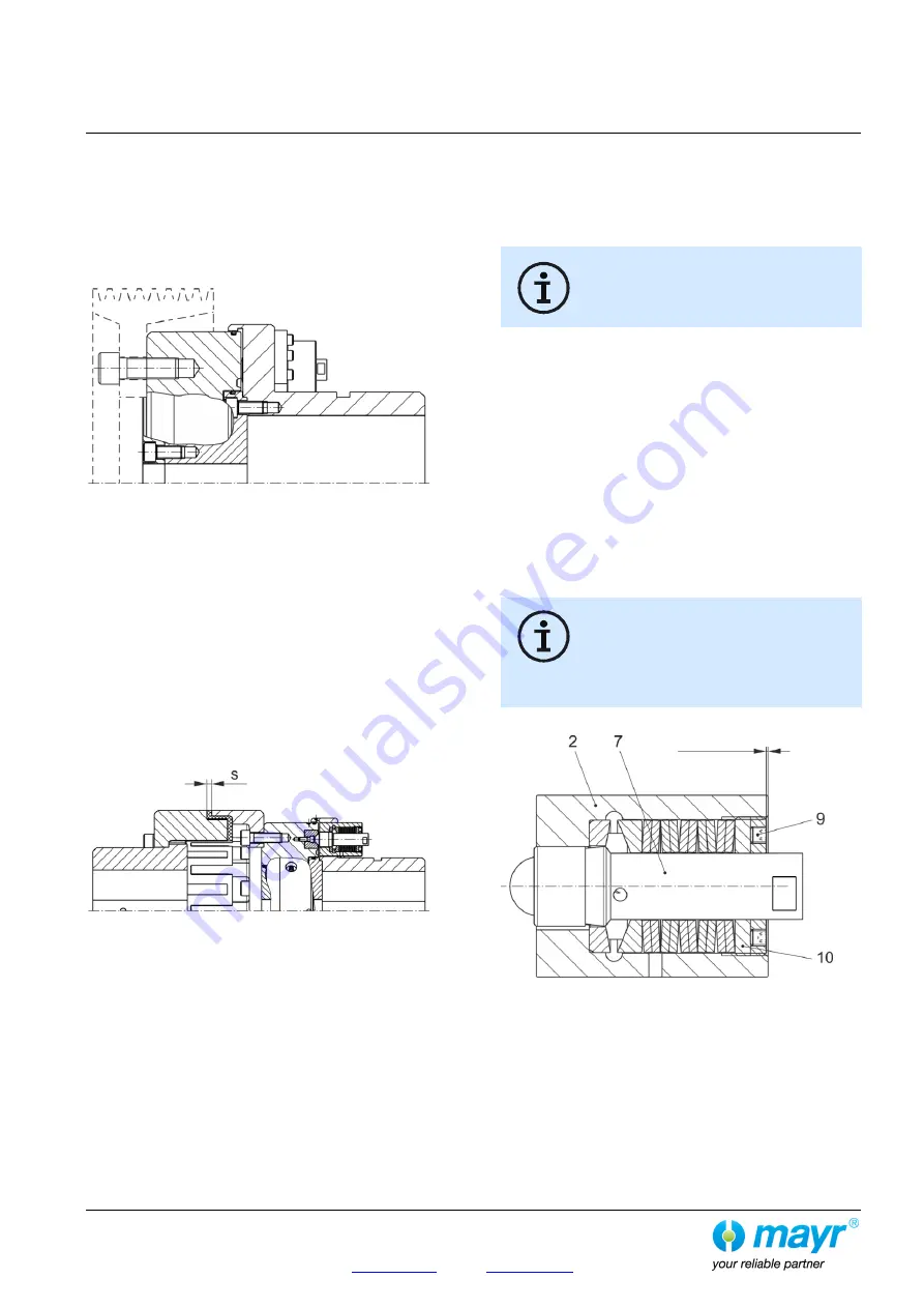
Torque Adjustment (Fig. 8)
Set the limit torque M
G
for overload on the clutch by changing
the cup spring pre-tension on each overload element (2)
according to the Adjustment Diagram.
On the clutches the adjusting nut (9) is adjusted by turning it in
the overload element (2) using a face wrench.
During torque adjustment, please ensure that
all overload elements (2) on the clutch are
evenly adjusted!
Torque Adjustment:
1. Determine the limit torque M
G
for overload.
2.
Please determine dimension “a” using the Adjustment
Diagram included in the clutch delivery.
This dimension is equal to the required limit torque M
G
.
3.
If necessary, unscrew the switching disk
(23) and remove
the cap screws (24).
4.
Loosen the locking set screws (10) on the
adjus
ting nuts (9).
5. Set all overload elements (2) by turning the adjusting nut (9)
to the dimension “a” (Fig. 9) found in the Adjustment
Diagram.
6.
Tighten the locking set screws (10) again in the
adjusting
nuts (9).
7.
If necessary, screw the
cap screws (24) via the switching
disk (23) in the bolts (7); then tighten them with a tightening
torque acc. Table 3.
In order to guarantee low-wear clutch operation,
it is essential that the clutch torque is set to a
sufficiently high service factor (overload torque to
operating torque). Our experience has shown
that an adjustment factor of 1.5 to 4 gives good
results. On very high load alternations, high accelerations and
irregular operation, please set the adjustment factor higher.
Fig. 9
Dim. “a”


