


Installation and Operating Instructions for
EAS
®
-compact
®
clutch Type 493._ 4 _ .0 Sizes 01 – 1
(B.4.16.GB)
10/03/2005 K/TK/Kr
Chr. Mayr GmbH + Co. KG
Tel.: 08341 / 804-0
Eichenstraße 1
Fax: 08341 / 804-421
87665 Mauerstetten
http://www.mayr.de
Page 3 of 5
Germany
eMail:
Design:
The EAS
-compact
®
clutch combined with a torsionally rigid
smartflex
-steel bellows coupling is a torque limiter in combination
with a steel bellows-shaft coupling for connection of two shafts
with alignment ability of shaft misalignments. The steel bellows
coupling compensates axial, radial and angular shaft
misalignments (Table 2, Figs. 6 and 7). The total amount of
misalignments must not exceed 100 %.
Supply condition:
The EAS
-compact
®
clutch is completely assembled, including the
clamping nut (9) for backlash-free shaft fitting and is set to approx.
70 % of the corresponding max. torque, if the customer does not
request any other torque adjustment.
The fits for the hub (1) and bushing (12) are H7 as standard. h6
fits are recommended for the shafts. Please contact the
factory in case of other fits.
The locking screw (11) is not secured with Loctite in case of a
preset clutch. Secure the locking screw (11) with Loctite 243
before an initial start-up of the clutch.
Check supply condition!
Function:
During operation the torque is transmitted from the motor shaft to
the output shaft via the EAS
®
- clutch and all-steel bellows
coupling. In case of an overload the clutch disengages, the thrust
washer (3) moves axially, a limit switch (18) scans this movement
and provides a signal to switch off the drive.
The residual torque amounts to approx. 5 – 15 % (with approx.
1500 rpm).
The EAS
-compact
®
clutch is consequently only conditionally load
holding. The clutch is automatically ready for operation after
removing the overload.
Re-engagement:
EAS
-compact
®
Ratcheting clutch Type 493._ 40.0 after 15°
EAS
-compact
®
Synchronous clutch Type 493._ 45.0 after 360°
Important mounting instructions
Bores, shafts, hubs and steel bellows must not be oiled or
greased.
Cap screws (10 and 14.3) must be unscrewed.
Avoid damages to the steel bellows (15) before and during
assembly.
Clamping ring (14.1) together with spring (14.2) must be
engaged in the bushing (12).
A smartflex
-unit (components 12, 14, 15) may be assembled
or disassembled 5 times maximum (otherwise there are
unacceptable deformations of the groove in the bushing (12)).
Dismantling of the smartflex
-unit by simply pressing the
bushing (12) out of the clamping ring (14.1) (manually or at a
small hand-operated press).
Dismantling of the EAS
- unit is made after unscrewing the
cap screws (10) and (14.3 EAS
- side) by simply drawing off
the shaft.
Assembly
Fix the EAS
-compact
®
clutch axially after pushing the clutch
onto the shaft which is made via tightening the cap screw
(10) in the tightening nut (9) with the prescribed tightening
torque (Table 1).
Push the other shaft into the smartflex
-unit (components 12,
14, 15) until the required position is achieved and fix it axially
by tightening the cap screw (14.3) with the prescribed
tightening torque (Table 1).
Table 1
Size
01
0
1
Tightening torque
Cap screw (10)
[Nm]
16
40
79
Tightening torque
Cap screw (14.3)
[Nm]
17 ±5 % 17 ±5 % 41 ±5 %
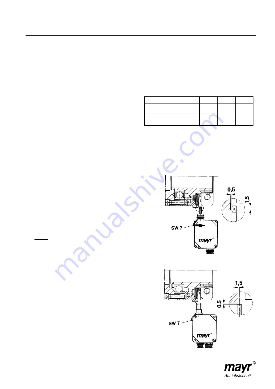
Fitting the limit switch (Figs. 2 and 3):
The switch direction located at the housing cover of the
mechanical limit switch points in the direction of the clamping nut
(9) or in stroke direction of the thrust washer (3). Adjust the switch
distances for the mechanical and contactless limit switch acc. to
Figs. 2 or 3. The distance of the thrust washer (3) from the switch
point can be sensitively adjusted with a hexagon head cap screw
SW 7.
Fig. 2
Fig. 3
Switch
direction