Installation and Operational Instructions for
EAS
®
-lastic clutches Type 437._ _ _.0
(B.4.11.GB)
23/05/2006 K/TK/GC/RJ
Chr. Mayr GmbH + Co. KG
Tel.: 08341 / 804-0
Eichenstraße 1
Fax: 08341 / 804-421
87665 Mauerstetten
http://www.mayr.de
Page 2 of 3
Germany
eMail:
Function
EAS
®
-lastic clutches are positive-locking, torque-limiting
overload clutches used to connect two shafts.
Under compensation of longitudinal, transverse or angular
misalignment, the EAS
®
-lastic is capable of transmitting the
torque from the input to the output safely and reliably in normal
operation. On overload or on reaching the set limit torque, the
clutch immediately separates input and output. The mayr
®
-limit
switch registers the overload and transmits a signal to stop the
drive or other control functions.
Designs
1. EAS
®
-lastic ratchetting clutch Type 437._00.0
On overload, this device ratchets and gives electrical contact
free to stop the drive. As it is ratchetting, the torque is much
lower than the set disengagement torque. Re-engagement takes
place automatically.
2. EAS
®
-lastic synchronous clutch Type 437._05.0
On overload, this device gives an electrical contact free to stop
the drive, releases it mechanically and then connects the drive
elements after one turn (360°) mechanically again. Re-
engagement takes place automatically at the same point at
which it disengaged.
3. EAS
®
-lastic overload clutch Type 437._14.0
On overload, this device switches off the drive electrically and
disengages mechanically on free run-out. Re-engagement takes
place manually or via a re-engagement device.
4. EAS
®
-lastic synchronous overload clutch Type 437._03.0
On overload, this device switches off the drive electrically and
disengages mechanically on free run-out. Re-engagement takes
place manually or via a re-engagement device to re-engage after
a 360° turn at the same point at which it disengage d.
5. EAS
®
-lastic torque sensor clutch Type 437._01.0
On overload, this device gives an electrical contact free or a
signal to stop the drive. However, this component continues to
transmit the torque mechanically. Re-engagement takes place
automatically.
Characteristics of Individual Designs
On the overload clutch, the synchronous overload clutch, the
ratchetting clutch and the synchronous clutch, please observe
the starting torques. High speeds can therefore only be reached
by gradual speed increase, otherwise the clutch will disengage in
the start-up phase and stop the drive.
On the EAS
®
-torque sensor clutch, the limit switch must be
bridged during start-up, in case the starting torque is higher than
the set clutch torque. Otherwise the clutch will disengage during
start-up.
Limit Switch
On overload, the mayr
®
-limit switch registers the clutch
disengagement quickly and precisely and emits a signal to
switch off the drive or other control functions (for more, see
catalogue K.407.0_.GB).
Clutch / Coupling Installation
The flexible coupling is designed as a simple plug coupling. The
pocket element (4) on the flexible coupling and the EAS
®
-clutch
(1) are pushed onto the shaft and fixed axially e.g. with a press
cover or a set screw. The coupling bores are standard-fitted with
an H7 tolerance. (Tolerance of keyways JS9).
We recommend a k6 tolerance for the shaft.
Warning!
If the EAS
®
-clutch part (1) is delivered pilot bored, the
claw element (2) will only be partly assembled,
meaning that the fixing screws (2.1) are lightly
tightened.
After finish-boring the EAS
®
-clutch part, (1) the fixing
screws (2.1) must be tightened to the torque shown in
Table 1 and secured using Loctite 243 (medium hard).
Assembly of the Coupling Halves
The rubber buffers (3) are pressed into the pocket element (4)
and greased lightly. The claw element (2) is designed so that
there is no backlash between the claw and the rubber buffer (3),
but rather a light pre-tension. This means that some axial force is
needed to push the coupling halves together. The force needed
can be greatly decreased by putting a thin layer of acid-free
grease onto the claws of the claw element (2).
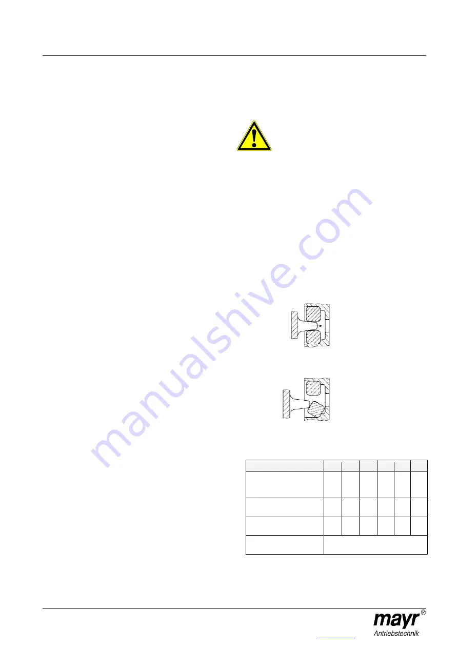
When joining the coupling halves, please make sure that the
claws are between and not on the rubber buffer, or the rubber
buffer may tilt (see Fig. 2). Also, please make sure that the
distance dimension “Z” is observed (see Table 1 or Fig. 1) when
joining the coupling halves, otherwise the permitted
misalignment possibilities become very limited.
Fig. 2
Table 1
Size
0
1
2
3
4
5
Tightening torque for
fixing screws
(Item 2.1, Fig. 1)
[Nm]
5.5
5.5
9.5
23
46
80
Distance dimension „Z“
(Fig. 1)
[mm]
4
4
4
4
4
4
Number of
rubber buffers
12
12
12
12
12
12
Temperature resistance
of rubber buffer
+90 °C / -30 °C
Correct
Incorrect


