Mayline 5 COLUMN CRNR XR BASE Assembly Instructions Download Page 5

(5)

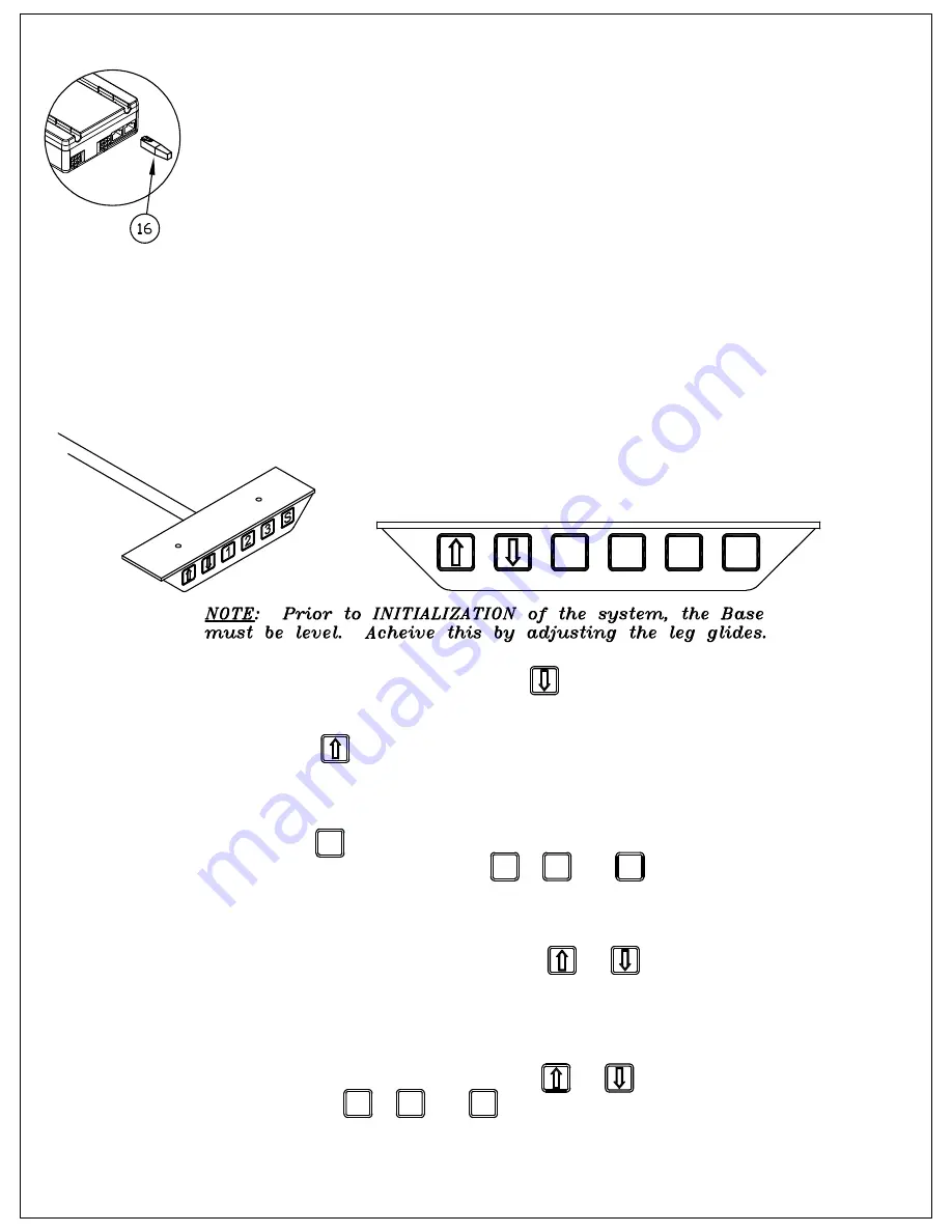
15. Attach Anti Collision Dongle Option (when ordered).

To install the Anti Collision Dongle (16), simply plug the dongle into one of the two
control (switch) ports on the Control Box (10,11).  The function is only active when
the dongle is mounted - if you remove the dongle you disable the function.

Note: Situations where anti-collision does not work.

1) If the collision happens during the initialization stage.

2) If the collision happens within the first 1000 msec or after the control button has

been released.
3) If the collision time span is too long, i.e. if the collision is with a soft object.

INSTRUCTIONS  for

DESK SWITCH w/ PROGRAMMABLE

MEMORY

1. Initialize system by pressing down        and holding for 5 to 10

    seconds after table bottoms out.

2. Push 'UP'         to desired height.

3. To save this position in Memory:

    A.) Press        (Set)
    B.) Press (do not hold) button        ,         , or

    Position is now saved under the number chosen.

4. To change to different height, press         or         .
    This position may be saved by repeating Step 3 and using
    one of the other buttons or using the same button to change
    the previous setting.  Up to 3 positions may be stored.

5. To go to new height position, press         or         , or press stored

    height under        ,         , or       .  Unit will automatically stop at
    the stored position.

S

1

3

2

1

2

3

2

1

3

S

Summary of Contents for 5 COLUMN CRNR XR BASE

Page 1: ...W X12 E6 4 6 X 5 8 SCREW X10 E7 12 1 4 20 X 1 2 SCREW X352 E8 12 1 4 20 KEPS NUT T126 E9 8 CABLE CLAMP F191 E10 4 8 x 1 75 SCREW X533 COMPONENTS REF QTY DESCRIPTION PART No 1 5 LIFT ACTUATOR Z460 2 2 XR FOOT 30 A8174 3 1 XR FOOT 14 A7299 4 1 ACT SUPPORT LEFT A8176 5 1 ACT SUPPORT RIGHT A8177 6 1 BRACKET ASM CORNER A7292 7 1 CHANNEL CROSS 520CC 50 520CC 01 40 8 3 TOP PLATE B6969 9 2 TOP PLATE 14 B8...

Page 2: ...he Actuator Column 1 with four M6 x 16 mm Screws E1 and Star Washers E2 Attached two Glides E3 to bottom of foot 6 Place the assembled columns upright and attach the Left 4 and Right 5 Actuator Supports between the Columns Position the Supports so the Channel Brackets face toward each other Slide the Support brackets onto the tapered support clip on each Actuator Column Gently tap the Act Supports...

Page 3: ... and Corner Bracket 6 and with 1 4 20 X 1 2 Screws E7 and 1 4 20 KEPS Nuts E8 Note 4 screws are used in Corner Bracket and 2 into Support Channel 10 Attach Memory Switch 12 and Main Cable 13 to Control Boxes 10 and 11 Attach 1ea 2500mm Motor Cable 15 and 1000mm Motor Cable 14 to the 2 Port Control Box 10 Attach 2ea 2500mm Motor Cable and 1ea 1000mm Motor Cable to 3 Port Control Box 11 ...

Page 4: ... a minimal thickness of 1 inch 25 4mm 11 Align the holes in the Tops with the holes in the Top Plates 8 9 and secure in place with eight 10 x 1 Screws E5 12 Choose a desired location for the Control Boxes 10 11 and attach with two 8 x 1 3 4 Screws E10 per Control Box Connect the motor cables to the columns 13 Place the Memory Switche s ze 12 in a comfortable and accessible location on the undersid...

Page 5: ...n time span is too long i e if the collision is with a soft object INSTRUCTIONS for DESK SWITCH w PROGRAMMABLE MEMORY 1 Initialize system by pressing down and holding for 5 to 10 seconds after table bottoms out 2 Push UP to desired height 3 To save this position in Memory A Press Set B Press do not hold button or Position is now saved under the number chosen 4 To change to different height press o...

Reviews: