Maxtor Digital Multiplex Recorder User Manual Download Page 36

32

In DMR MENU / NETWORK  set SERVER IP, GATEWAY, NET MASK, DNS and WEB PORT.   

Step 5 : IP setting

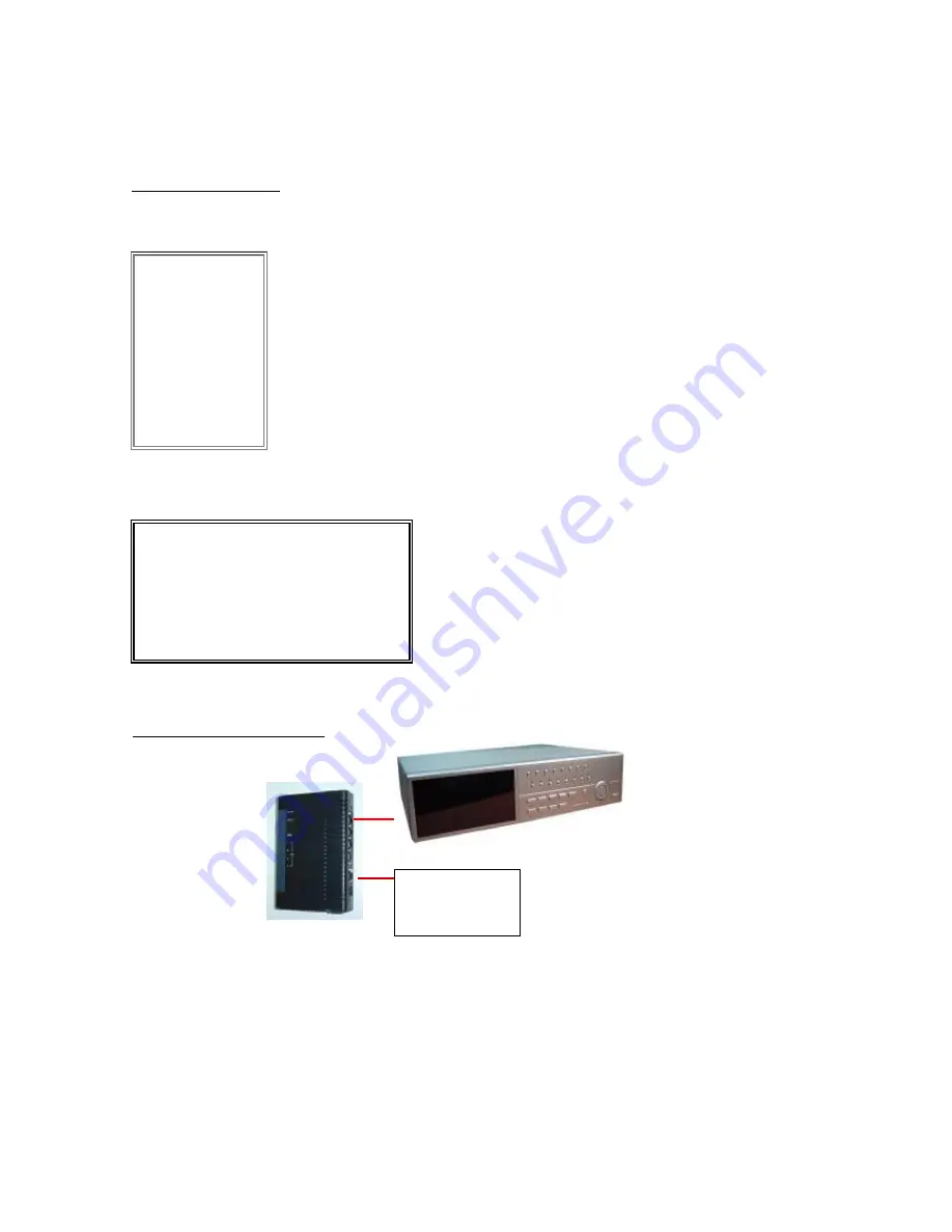
Step6 : Connect router

For example

(MENU)

SEARCH
TIMER
RECORD
CAMERA    
SYSTEM
EVENT
NETWORK

(NETWORK)

SERVER IP    
GATEWAY   
NET MASK   
DNS              
WEB PORT 
RESET DEFAULT  NO

ADSL modem

(WAN end)

192.168.001.010
192.168.001.065
255.255.255.000
168.095.001.001
00080

Summary of Contents for Digital Multiplex Recorder

Page 1: ...Digital Multiplex Recorder USER S MANUAL 777 W V1 0 Please read the instructions thoroughly before operation and retain it for future reference ...

Page 2: ...he appliance All the safety and operating instructions should be read before operation The improper operation may cause permanent damage Please use the provided adaptor Other adaptor is not suitable for this machine Please lift and place this equipment gently Do not expose this equipment to open sunlight Do not use this equipment near water or in contact with water Do not spill liquid of any kind ...

Page 3: ... Setup Detailed Menu Setup MENU ACCESS MENU MAIN MENU MENU OPTIONS MOTION DETECTION Network Setting Guide Network Setting Guide HARDWARE CONNECTION AT DMR SIDE STATIC IP SETTING DYNAMIC IP SETTING SOFTWARE OPERATION AT CLIENT SIDE INTRODUCTION OF BASIC OPERATION PLAYBACK OPERATION ADVANCED SETTING CONNECT VIDEO WEB SERVER VIA IE BROWSER TABLE OF CONTENTS 1 1 2 3 5 6 6 8 9 9 10 15 17 18 224 34 35 3...

Page 4: ...peration Advanced Operation OPERATION OPTIONS KEY LOCK TROUBLE SHOOTING SPECIFICATIONS Appendix Appendix APPENDIX 1 INSTALL HDD APPENDIX 2 RACK MOUNT APPENDIX 3 RECORDING SPEED APPENDIX 4 PIN CONFIGURATIONS 43 44 44 45 46 48 49 50 ...

Page 5: ...quality adjustable on each channel Alarm Input Output Function Video loss detected on each channel can record up to 160 events Power loss memory function Support 2 Removable HDDs IDE Type Quick Multiple Search by date time alarm full list Security password protection 1 What Do You Get What Do You Get Digital Multiplex Recorder with HDD cartridge User s Manual 2 Keys for Cartridge Power Adapter and...

Page 6: ...0rpm HITACHI Deskstar 7K250 HDS722525VLAT80 250GB 7200rpm IBM Deskstar 120GXP 80GB 80GB 7200 rpm IBM Deskstar 120GXP 120GB 120GB 7200 rpm Maxtor DiamondMax 536DX 60GB 4W060H4 60GB 5400rpm Maxtor DiamondMax Plus 9 80GB 7200 rpm Maxtor DiamondMax Plus 9 Model 6Y120L 120GB 7200 rpm Maxtor DiamondMax Plus 9 Model 6Y160L0 160GB 7200rpm Seagate Barracuda ATA IV ST380021A 80GB 7200rpm Seagate Barracuda A...

Page 7: ... refer to page 46 Appendix 1 2 MENU Press MENU button to enter main menu 3 ENTER Press ENTER button for confirmation 4 ZOOM Press ZOOM button to enlarge the picture display 5 Press PIP button for Picture in Picture screen 6 SLOW To slow down speed of play mode 7 SELECT Press SELECT button to select appointed camera 1 16 to display on full screen mode 8 4 channels display mode ...

Page 8: ...ss REC to start recording 14 REW LEFT REW Under DMR play mode it can play video backward at different speeds Press REW again to adjust speed as 1 2 4 8 16 32 times Left Under setup mode it works as Left button 15 PLAY Press PLAY to play recorded video 16 STOP DOWN STOP Under DMR Record Play mode it can stop the action DOWN Under setup mode it works as Down button 17 PAUSE UP Pause Under DMR play m...

Page 9: ... Connect video signal between Input port and Loop port to make a loop 6 AUDIO IN 1 4 Connect to audio source such as microphone IPS should be set to 25A for NTSC or 18A for PAL 4 audio inputs but users can only select 1 for recording 7 AUDIO OUT R L Connect to monitor or speaker IPS should be set to 25A for NTSC or 18A for PAL with 2 mono audio outputs from the same source 8 MONITOR Connect to Mai...

Page 10: ...ding status if power is off accidentally recorded video will still be stored in the HDDs DMR will return to original recording situation after power is on again On the screen you will find the date time HDD recording type the amount of available GB left in the HDDs memory and the letter M represents the method of recording that is occurring OW HDD Overwrite NOTE 1 When the HDDs are full under O W ...

Page 11: ... Slow mode Press once to get 1 2X speed forward and press twice to get 1 4X speed and the slowest speed can reach 1 32X Press once to get 1 2X speed rewind and press twice to get 1 4X speed and the slowest speed can reach 1 32X 3 PAUSE It will let you pause the current image displayed on the screen 4 STOP Press STOP button under all circumstance it will return DMR to live monitoring mode 5 IMAGE J...

Page 12: ...LARM REC IPS A LARM REC QUA LITY MO TION TRIG GER RECORD RECORD TITLE DWELL Brightness Contrast C olor ALA RM RECO RD CAMERA AU DIO INPUT INT AUD IBLE ALARM EX T AUDIBLE ALARM MOTION AU DIBLE ALARM A LARM DUR ATION DWELL TIME MESSAG E LATCH TITLE DISPLAY TIME D ISPLAY TIME N EW PASSWO RD CLEAR H DD SY STEM RESET SY STEM EVENT SEVER IP GATEWAY NET MASK DNS WEB PORT RESET DEFAULT NETWORK MENU ...

Page 13: ...sword Error you might enter an incorrect password There are 7 options available in the Main Menu SEARCH Find recorded list TIMER Scheduling Record RECORD Record Mode Setup CAMERA Camera Channel Setup SYSTEM System Setup EVENT Event List NETWORK Network Setup 9 Outlined below are the buttons used for Menu setting Up and Down Scroll up and down or change values when an option is selected and is blin...

Page 14: ...en NO is the default setting which the messages will go away after 10 sec NOTE Video loss Alarm and Motion messages will be shown the same as Alarm Duration time 8 TITLE DISPLAY To set the title shown on monitor or not 9 TIME DISPLAY To set the time format on the DMR 10 TIME To set the correct time on the DMR 3 EXT AUDIBLE ALARM To set the EXTERNAL AUDIBLE ALARM It will be trigged by event occurre...

Page 15: ... Motion Recording M Manual Recording time A Alarm Recording time T Timer Recording time M HDD Storage in Master HDD S HDD Storage in Slave HDD 3 ALARM LIST Show a listing of all recorded video triggered by an Alarm NOTE If there is no Alarm recorded the screen will display EMPTY 4 MOTION LIST Show a listing of all triggered motion detections 5 TIME SEARCH Find video recorded on a specific date tha...

Page 16: ...e from every Sunday 11 30 to Monday 00 20 then you should set Recording Timer Schedule as Sunday from 11 30 to 23 59 and Monday from 00 00 to 00 20 2 START Select the starting time for the recording 3 END Select the finishing time for the recording 4 QUALITY Select the image quality for the recording There are four Quality settings BEST HIGH NORMAL and BASIC 5 IPS Stand for Images Per Second and i...

Page 17: ...xample when the alarm duration setting is 1 min the time recording time is from 9 00 00 to 9 01 00 If the motion detection trigged again at 9 00 40 the trigged recording time will from 9 00 00 to 9 00 40 and 9 00 40 to 9 01 40 The total recording time is 00 01 40 2 Select OFF The screen shows the motion detection will change the scanning sequence while in recording mode and shows M on the monitor ...

Page 18: ...e the digit Press the MENU button to confirm the changes to exit the menu Set IP ADDRESS GATEWAY NET MASK DNS and PORT Choose YES in RESET DEFAULT will go back to default value of NETWORK 14 NETWORK SERVER IP GATEWAY NET MASK DNS WEB PORT RESET DEFAULT NO 192 168 001 010 192 168 001 065 255 255 255 000 168 095 001 001 00080 ...

Page 19: ...screen ON or OFF Figure 1 3 5 Press SLOW button to setup the Sensitivity list up to 255 and REC button to setup the Sensitivity list down to 000 The default value is set on 32 NOTE Sensitivity value is related to motion and brightness change Low value as 001 means higher sensitivity on motion and brightness change High value as 255 means lower sensitivity on motion and brightness change User can c...

Page 20: ...002 JAN 01 03 00 00 M HDD LOSS 2002 JAN 01 03 00 00 M HDD ERROR 2002 JAN 01 03 00 00 S HDD WARNING 2002 JAN 01 03 00 00 HDD FULL 2002 JAN 01 03 00 00 SYSTEM ERROR 2002 JAN 01 03 00 00 02 VLOSS 2002 JAN 01 03 00 00 03 ALARM 2002 JAN 01 03 00 00 PAGE UP PAGE DOWN CLEAR M HDD WARNING Master HDD might be failed M HDD LOSS Master HDD does not exist Now user can use the other HDD M HDD ERROR Master HDD ...

Page 21: ...17 HARDWARE CONNECTION AT DMR SIDE Network Setting Guide Direct Connect with PC Direct Connect with PC Remote Connect Via Internet Remote Connect Via Internet PC CAMERA MONITOR CAMERA MONITOR PC ...

Page 22: ...TEP1 Software installation 1 Put the attached CD into a CD ROM and it will start to install the application program on Windows PC 2 Press Next STATIC IP SETTING 3 Choose destination location and press Next ...

Page 23: ...4 Set program shortcuts setting and press Next 5 Press Next to copy files 6 After the installation there are 6 files and 1 folder in your assigned path file folder as below 19 ...

Page 24: ...your local ISP internet service provider After all network settings are finished please connect DMR to internet MENU SEARCH TIMER RECORD CAMERA SYSTEM EVENT NETWORK 20 For example NETWORK SERVER IP GATEWAY NET MASK DNS WEB PORT RESET DEFAULT NO Static IP 61 66 138 74 61 66 138 254 255 255 255 000 168 095 001 001 00080 ...

Page 25: ... User name Password Note If you never change the Account before the default user name and password are both admin and Server IP which you have set to DMR in step 2 Then click OK to connect Step3 Connect PC and DMR via the internet ...

Page 26: ...MIC IP SETTING 22 3 Choose destination location and press Next Step1 Software installation 1 Put the attached CD into a CD ROM and it will start to install the application program on Windows PC 2 Press Next ...

Page 27: ...4 Set program shortcuts setting and press Next 5 Press Next to begin copying files 23 6 After the installation there are 6 files and 1 folder in your assigned path file folder as below ...

Page 28: ...Step2 DDNS apply 1 Click on free site http www dyndns org please look at the example below you can also apply DDNS in other DDNS web page and ACCOUNT 2 Press Create Account 24 ...

Page 29: ...ate Account 4 After registering your account you will receive an e mail which contains instructions to activate your account If you do not follow these directions within 48 hours you will need to re register your account 5 Login your account 25 ...

Page 30: ...d Host name is TEST And then press Add Host to finish the setting NOTE Some routers don t support some DDNS HOST Step3 Loginrouter 1 Connect PC and router LAN end NOTE The following settings are different from router to router Please read the instruction of your router thoroughly 26 POWER LAN end TEST ...

Page 31: ...e instruction is based on Win XP O S If your O S is Win 2000 or Win 2003 the setup procedure is similar to that of Win XP O S Click twice 3 Click Properties for TCP IP setup 27 Local Area Connection Enabled Realtek RTL8139 Family ...

Page 32: ...4 Click on INTERNET PROTOCAL TCP IP then select Properties to setup 5 Choose Obtain an IP address automatically 6 Enter Command Prompt 28 ...

Page 33: ... address router s gateway 192 168 1 1 to log in to the router from internet explore And then enter the login web page and key in the router s user name and password 7 In the setting window type ipconfig to find out router s gateway e q 192 168 1 1 29 ...

Page 34: ...efer to the user s manual of router 2 Press LOCAL PORT and set Start IP address and Number of IP address For example if the IP address of DMR is 192 168 1 10 then 10 is excluded from the setting range Press save after you finish setting up 30 1 Press INTERNER PORT and choose your WAN type e q PPPoE and then enter your User Name and Password of dialing up to dynamic IP Press save after you finish t...

Page 35: ...rt Number to 80 for DMR And set Local Server IP Address to 192 168 1 10 Press add after you finish the set up 4 In ADVANCED SETUP Dynamic DNS Key in the DNS Account User Name and Password that you applied in step 3 Press save after you finish the set up 31 TEST ...

Page 36: ...EB PORT Step 5 IP setting Step6 Connect router For example MENU SEARCH TIMER RECORD CAMERA SYSTEM EVENT NETWORK NETWORK SERVER IP GATEWAY NET MASK DNS WEB PORT RESET DEFAULT NO ADSL modem WAN end 192 168 001 010 192 168 001 065 255 255 255 000 168 095 001 001 00080 ...

Page 37: ...ake sure that you have pressed save after setting In step 6 Please use router s LAN end to connect to DMR Use WAN end to connect to ADSL modem In step 7 The Server IP is the DDNS HOST which you set in step 4 4 NOTE NOTE There are two ways to get the software one is via attached CD and the other is via Video Web Server Refer to P 41 42 vAddress Book You can press Address Book button to add a new IP...

Page 38: ...low the steps for connection at your client site remote site e g If you set up the server at your office with one static IP you can remotely proceed to watch the video anywhere with a networked computer Step 3 If you could see the video screen as following you have been successfully connecting to the server 34 For example SOFTWARE OPERATION AT CLIENT SIDE ...

Page 39: ... CIF 5 Image quality High Middle Low 6 Image adjusting Brightness Contrast Saturation 7 Snapshot press this button the image will be automatically saved in the PC 8 Record press this button the recording file will be saved in the PC automatically 9 System Config 10 Number of online users 1 2 3 4 5 6 7 8 9 10 INTRODUCTION OF BASIC OPERATION ...

Page 40: ...Left Right Up Down 6 Enter 7 TURBO uNOTE After you press the record icon there will be a recording file in the path that you have set Each recording file can be save up to 6000 frames The recording file will be assigned to the second File if it is more than 6000 frames Besides if the HDD space is less than 200MB the program will stop recording 36 1 2 6 7 3 4 5 ...

Page 41: ...X 6 PLAY 7 Fast 2X 4X 8X 16X 32X PLAYBACK OPERATION 37 8 OSD show hide 9 Config setting Path of snapshot text color progress color channel color 10 Open Last File 11 Open Next File 12 Duration time Status 13 Playback controlling bar 1 2 3 4 5 6 7 8 9 10 11 12 13 2004 12 15 09 49 38 2004 DEC 15 WED 09 49 33 Ad 001 4 GB O W NTSC_CIF 219 84 21 166 20 CH1 ...

Page 42: ...basic functions only GUEST LEVEL watch the image only 2 Life time During the period of time users are allowed to control the Video Web Server ACCOUNT 1 Alarm Trigger Enable or disable Alarm trigger function 2 Alarm Method Two selections E mail or FTP 3 Image Resolution Image storing resolution for Email or FTP function CIF is 176 144 D1 is 352 288 4 Alarm refresh Clean the alarm message which is s...

Page 43: ...will capture the instant picture and e mail the captured image to the assigned recipients MAIL 1 You can get all the data from your MIS department 2 The default uploading port is No 21 3 You can set the uploading directory FTP When the alarm is triggered the video server program will capture the instant picture and upload the captured image to the assigned FTP site File Path You can modify the sto...

Page 44: ... Firmware to upgrade it 2 Turbo Step Activate the turbo button when you would like to shift the selections more quickly by jumping 6 selections at a time Upgrade the firmware and get the online users information NOTE Do not reboot the DMR while it is upgrading the firmware The information of online user Info Refresh It can refresh the users information ...

Page 45: ...You can also connect Video Web Server via browser This function is suitable in both WIN 2000 and WIN XP WIN XP is preferable to WIN 2000 41 CONNECT VIDEO WEB SERVER VIA IE BROWSER Step 2 Enter your Username and Password to login Video Web Server 219 84 21 166 ...

Page 46: ...e 3 Video Channel 4 Resolution D1 CIF 5 Image quality High Middle Low 6 Number of online users 7 Channel switching button 8 Resolution switching button 9 Quality switching button 10 Menu Left Right Up Down Exit 11 Lock Enter Zoom Search Select 12 Stop Play Record Rew Fast Pause Slow 13 Camera 14 4cut 7cut 9cut 10cut 13cut 16cut Pip 15 Position of view ...

Page 47: ...utton to confirm the camera selection àPress Left or Right to choose background or insert screen àPress camera select 1 16 to select appointed camera into screen àPress Menu to exit ZOOM Press ZOOM button to enlarge the display of main picture It displays zoomed picture on main picture and a small window inserted The inserted window contains a movable 1 4 view size of the appointed camera àPress t...

Page 48: ...nd their solutions Please check them before calling your DMR dealer PROBLEM SOLUTION l Please Insert HDD l Please use the Key to lock the HDD Cartridge And press any key l Check power cord connections l Confirm that there is power at the outlet l Check if it is under Key Lock mode l Press MENU ENTER to exist Key Lock mode No recorded video l Check if the HDD is installed properly Timer Record enab...

Page 49: ...r camera NTSC 15 14 targets per camera PAL Motion Detect Sensitivity 256 Levels Video Loss Detection Yes Refresh Rate Up to 120 images sec for NTSC 100 images sec for PAL Recording Rate Up to 25 images sec for NTSC 18 images sec for PAL Dwell Time Programmable 1 10 Sec Picture in Picture Yes Movable Key Lock Yes Picture Zoom 2 2 Movable Camera Title 6 letters Video Adjustable Color Contrast Bright...

Page 50: ...ference 2 46 Remove the Cartridge Case from the DMR Remove the Cover from the Cartridge Casing à Unclip the release latch with the word OPEN printed beside it by gently pushing on the latch à Slide the cover off the Cartridge Casing 1 APPENDIX 1 INSTALL HDD Cartridge Casing Keyhole LED indicator lights Handle 3 Connect the HDD into the Cartridge Casing Please take the Hard Disk Drive and Connect t...

Page 51: ...If you do not lock the cabinet the DMR system will not function properly A locked B unlocked Note 1 If two HDDs are set up one should be selected as Master and the other should be selected as Slave 2 This product does not support hot swap Please power off the unit before removing HDD 3 Approved models and manufacturers of HDD listed in page 2 have been tested and proven compatible with this applia...

Page 52: ...48 Screws and brackets for rack mounting applications can be purchased as an optional accessory Side View with Rack Mount Front Angle with Rack Mount APPENDIX 2 RACK MOUNT ...

Page 53: ...ferent based on Record Speed and Record Quality Please refer to following table NTSC SYSTEM PAL SYSTEM Note Above data is from actual test data obtained from recording normal TV program Reference only APPENDIX 3 RECORDING SPEED ...

Page 54: ...t when Alarm triggered COM connect with NO EXTERNAL ALARM NO PIN 25 Under normal operation COM disconnect with NO But when Alarm triggered COM connect with NO EXTERNAL ALARM COM PIN10 11 12 14 23 24 PIN OFF PIN2 9 PIN 15 22 To connect wire from ALARM INPUT PIN 2 9 PIN 15 22 to GND PIN 1 connector DMR will start recording and buzzer will be on Ø When Menu Camera Alarm is set up to Low When alarm in...

Reviews: