


Introduction
This Quick Start Guide provides OEMs and integrators with an introduction to
some of the module's most important features. This guide provides step-by-step
instruction on how to setup a wireless link and test the module's ability to
transport data over varying ranges and conditions.
Double-click "setup_X-CTU.exe" file and follow prompts of the installation screens.
This file is located in the "software' folder of the MaxStream CD and under the
'Downloads' link of the following web page: www.maxstream.net/helpdesk/
Figure 1.
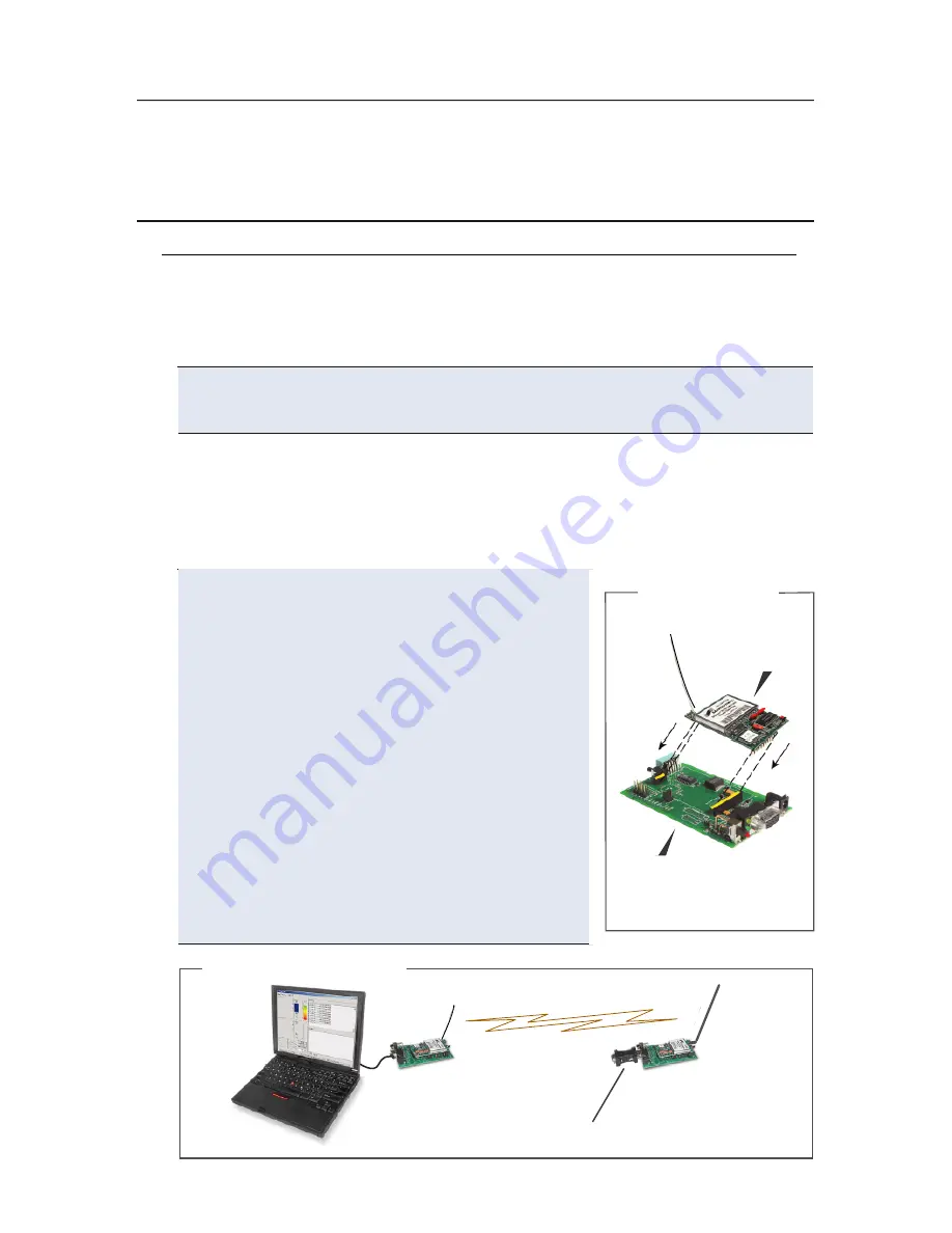
Module Assembly
MaxStream XIB-R
Interface Board
XStream
Module
Figure 2. Hardware Setup
Requirements for Range Test
Install X-CTU Software
2 OEM RF Modules
2 Interface Boards
Accessories (Loopback adapter, RS-232 cable, 2 antennas, 2 power supplies)
1 PC (Windows 98 SE, 2000 or XP) loaded with X-CTU Software
Hardware Setup
1. Set both Interface Board DIP Switches
to
RS-232 Mode
. Switch 1 is ON (up) and the
remaining 5 switches are OFF (down) [Figure 5].
2. Mount each
XStream Module
to a MaxStream
Interface Board
[Figure 1]. Assemblies will
be referred to as "Radio1" and "Radio2".
3. Attach RPSMA antenna to the XStream Module
that does not have an attached wire antenna.
4. Connect Radio1 to a PC using the included
RS-232 cable
[Figure 2].
5. Attach the
serial loopback adapter
to
the DB-9 serial connector of Radio2.
(The serial loopback adapter configures
Radio2 to function as a repeater by
looping data back into the module for
retransmission. [Figure 2])
6. Power Radio1 & Radio2 through the interface
boards using the included power supplies.
Radio1
(w/ wire antenna)
Radio2
(w/ RPSMA Antenna)
Serial loopback adapter
Range Test Setup
The X-CTU Software interface is divided into the four following tabs:
• PC Settings - Setup PC serial com ports to interface with the module assembly
• Range Test - Test module's range under varying conditions
• Terminal - Read/Set module parameters and monitor data communications
• Modem Configuration - Read/Set module parameters


