background image

Preparing for installation 


14 

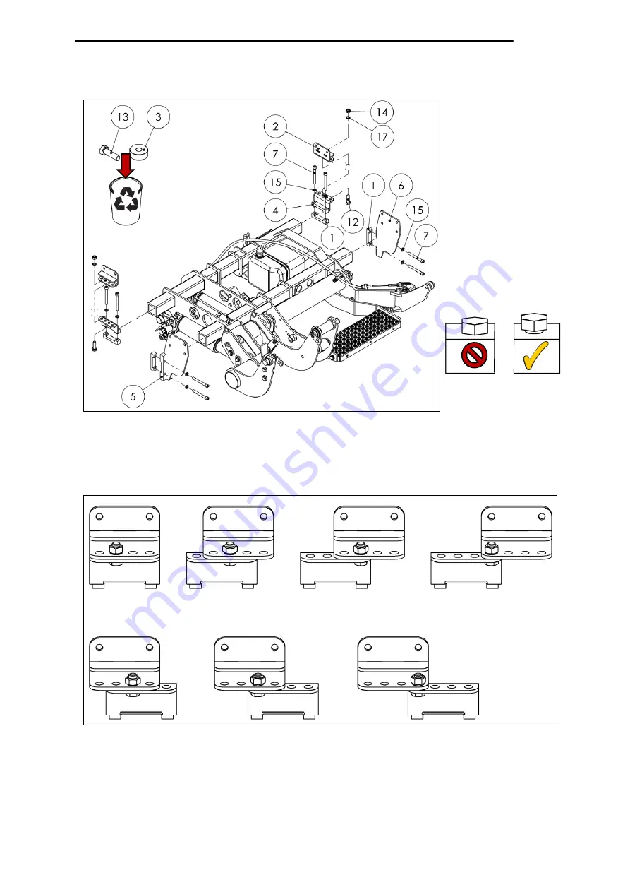
Vehicle with maximum authorized mass of 5 tons 

(for 3.5 ton vehicles, see previous page) 

Depending on requirements, different installation options are available for the front 
installation adapters (2 and 4) in the installation adapter kit (Part No. 22 911 216) 
(see Fig. 14). 


Fig. 13 


Fig. 14 


Summary of Contents for GPC X1-LDF

Page 1: ...GPC X1 LDF liftgate Installation Manual for Mercedes Benz Sprinter...

Page 2: ...LIFT CORP 11921 Slauson Avenue Santa Fe Springs CA 90670 2221 P 800 227 4116 562 464 0099 F 888 771 7713 Date 07 2019 Part No 20 912 027...

Page 3: ...information MAXON LIFT CORP Corporate Office 11921 Slauson Avenue Santa Fe Springs CA 90670 2221 P 800 227 4116 562 464 0099 F 888 771 7713 Customer Service Parts USA Canada Mexico P 800 227 4116 F 88...

Page 4: ...exhaust pipe 10 3 3 3 Mount supplementary battery 10 3 3 4 Install standard bumper on Mercedes Sprinter 10 3 3 5 Deactivate parking sensors 10 3 3 6 Remove trailer hitch or step 11 3 4 Unpacking the...

Page 5: ...the warning flags 45 4 18Affixing the danger notice sticker 48 5 Adjusting the liftgate 49 5 1 Setting the lift height to the vehicle floor level using the adjustable stop on the axle assembly 49 5 2...

Page 6: ...g the lifting gear 62 7 3 Rating plate 62 8 Useful information 63 8 1 About the service switch 63 8 2 Assembly drawings of installation adapters 65 8 3 Electrical circuit diagram 66 8 4 Hydraulic circ...

Page 7: ...formation on transport installation and commissioning Read this manual before working on or operating the liftgate Do not deviate from the instructions contained in this manual By doing so you risk in...

Page 8: ...hicle s on board power supply max 48 V DC The electrical system is designed using state of the art technology Do not damage or modify electrical components or wiring High pressure hydraulic system The...

Page 9: ...and complications WARNING Failure to heed this notice can result in death or serious injury CAUTION Failure to heed this notice can result in minor or moderate injury NOTICE Failure to heed this notic...

Page 10: ...uction 2 1 Scope of delivery IMPORTANT All illustrations of the lifting gear are shown without factory installed cables and hydraulic hoses 2 1 1 Lifting gear 2 1 2 Platform 2 1 3 Bridge plates 20 909...

Page 11: ...Introduction 5 2 1 4 Accessories kit Fig 4...

Page 12: ...sher DIN 9021 D5 3 A2 4 10 20 840 117 O ring 40 65x5 33 6 11 20 906 975 12 m cable with VEHH connector 1 12 20 906 974 Cabin switch 1 13 20 840 405 Lubricating grease 1 14 60 710 330 Warning flag Kit...

Page 13: ...Introduction 7 2 1 5 Installation adapter kit 22 911 216 Fig 5...

Page 14: ...socket DIN 912 M10x90 8 8 ZN PRE80 8 8 20 911 796 Hexagon flange bolt MBN 10105 M12x1 5x100 10 9 DBL 8 9 20 911 797 Hexagon nut with flange and clamping piece MBN 13023 M12x1 5 10 DBL 8 10 20 911 864...

Page 15: ...function correctly once the platform is installed because the lifting gear interferes with the sensors CAUTION Unsuitable transport equipment When transporting and lifting heavy parts use transport e...

Page 16: ...NOTICE Be sure to maintain a sufficient distance from heat sensitive parts The minimum distance from plastics and cables is 300 mm see Fig 7 3 3 3 Mount supplementary battery If applicable mount a sup...

Page 17: ...carefully After disposing of packing materials store all parts in a secured manner NOTICE Oil leakage Incorrect positioning of the lifting gear can result in oil leakage Risk of environmental damage A...

Page 18: ...ZFSHL 2 13 80 000 032 Hexagon head screw DIN 933 M12x40 8 8 A2K 2 14 80 000 050 Hexagon nut DIN 934 M12 8 A2K 2 15 80 000 061 Spring washer DIN 127 A 10 ZN 8 Pre install the installation adapters on t...

Page 19: ...ng for installation 13 Depending on requirements different installation options are available for the front installation adapters 2 and 4 in the installation adapter kit Part No 22 911 216 see Fig 12...

Page 20: ...thorized mass of 5 tons for 3 5 ton vehicles see previous page Depending on requirements different installation options are available for the front installation adapters 2 and 4 in the installation ad...

Page 21: ...placed in slings Fig 15 3 6 1 Cable to the platform Route the control unit cable for platform connection white plastic cover to the swing arm assembly in the center of the vehicle Fig 16 3 6 2 Cable f...

Page 22: ...n installing cables make sure they are safe from chafing Do not install cables near heat dissipating components With preparation according to ETMA Code A and Code B Route the power cable and the cable...

Page 23: ...into a length of slit corrugated tubing see Fig 19 NOTICE Do not yet connect the cables Route the positive cable red and negative cable blue to the terminals but do not yet connect them see Fig 20 Leg...

Page 24: ...to the 7 pin connector DIN 72585 from the control unit Fig 21 Legend Item 1 7 pin connector DIN 72585 from control unit Item 2 Connector for cabin switch unit Part No 20 910 754 3 6 4 Control panel ca...

Page 25: ...Sever the control unit cable 1 red marking with cable tie for connecting the handheld control see Fig 23 Leave the end without a cable tie blank Strip the end of the control unit cable section with a...

Page 26: ...allation location for the handheld control and route the cable to the installation location see Fig 25 Find the bushing into the cargo area 3 7 Aligning the lifting gear Align the lifting gear under t...

Page 27: ...e vehicle manufacturer s installation guidelines Find the mounting holes on the vehicle Make any new mounting holes that are necessary If necessary weld spacer sleeves onto the vehicle chassis Remove...

Page 28: ...llation 22 4 Installation 4 1 Positioning the lifting gear Place the prepared lifting gear on a pallet under the vehicle using a suitable means of transport e g pallet truck forklift etc see Fig 28 Fi...

Page 29: ...and vehicle Raise the lifting gear Insert the rear bolts installation adapter kit Part No 22 911 216 as viewed in the forward direction of travel and tighten until hand tight as shown in Fig 29 NOTICE...

Page 30: ...own in Fig 30 NOTICE Do not damage cables Excerpt from parts list Installation adapter kit Part No 22 911 216 Item No Part No Description Standard Qty 10 20 911 864 Hexagon nut with flange and clampin...

Page 31: ...g 31 NOTICE Do not damage cables Legend a Welded on bushing as per manufacturer s installation guidelines Excerpt from parts list Installation adapter kit Part No 22 911 216 Item No Part No Descriptio...

Page 32: ...Installation 26 4 3 Securing the lifting gear to the vehicle Secure the lifting gear with adapters to the vehicle and tighten to a torque of 115 Nm in the rear and 70 Nm in front see Fig 32 Fig 32...

Page 33: ...collide with the platform see Fig 33 4 5 Securing the axle assemblies Secure the installation adapters to the lifting gear and tighten to the specified torque of 53 Nm see Fig 34 4 6 Securing the inst...

Page 34: ...able by loosening the screw terminals in the housing see Fig 36 Legend Terminal 30 Black cable Terminal Y1 Blue cable Terminal KM Gray cable Terminal YA Brown cable Terminal Y3 Green yellow cable Rout...

Page 35: ...e to the control panel only from below Mount the control panel on door Route the control panel cable to the cargo area so that it can be secured to the right hand door a protect against kinks and ensu...

Page 36: ...control panel Using the release tool release the safety guard from the socket housing and pin housing see Fig 40 and Fig 41 For the socket housing release the latches on the contact pins and pull the...

Page 37: ...pin housing release the latches on the contact pins and pull the wires out of the back of the housing Fig 45 and Fig 46 Reassemble the control panel SUPERSEAL connector and the control unit SUPERSEAL...

Page 38: ...using the fasteners 1 6 9 from the accessories kit maintaining a distance of 400 mm 100 mm 15 1 15 16 as per specifications see Fig 37 und Fig 48 Required material from accessories kit Item No Part No...

Page 39: ...or the handheld control optional Mount the bracket 1 for the handheld control 2 on the vehicle wall 3 using for example 2 screws or adhesive see Fig 50 Legend Item 1 Bracket for handheld control Item...

Page 40: ...reparation according to ETMA Code A and Code B Connect the power cable and the cable for the cabin switch unit to the sockets provided see Fig 51 NOTICE Connect cables only to cables of the same color...

Page 41: ...abin switch unit Drill a 16 mm dia hole for the cabin switch 12 in a suitable location on the dashboard Snap the cabin switch 12 into the hole Route the cabin switch unit cable 11 from the lifting gea...

Page 42: ...delivery for completeness see pages 4f IMPORTANT Dispose of all packing materials in accordance with environmental regulations 4 9 Raising the platform Lift the platform using suitable means e g cran...

Page 43: ...ween the platform and lifting gear Remove the transport lock cable tie R e m ov e th e pi ns a b c s ee Fig 55 Legend Item a Pin Part No 20 905 057 Item b Pin Part No 20 840 722 Item c Pin Part No 20...

Page 44: ...57 Legend Item 1 Platform stop Thoroughly grease the bearing bushes with the special assembly grease accessories kit parts list Item No 13 see Fig 58 Excerpt from parts list accessories kit Item No P...

Page 45: ...s of the platform and the attachment points of the swing arm assembly IMPORTANT Note the direction of insertion see Fig 60 Mount the bolts from the accessories kit 2 to secure the pins and tighten the...

Page 46: ...t on the platform see Fig 61 IMPORTANT If necessary slightly retract or extend the closing rod Insert the pin c Mount the screw 8 from the accessories kit to secure the pin Fig 62 Excerpt from parts l...

Page 47: ...ll bearing points are sealed with O rings Excerpt from parts list accessories kit Item No Part No Description Standard Qty 10 20 840 117 O ring 40 65 x 5 33 6 4 11 Mounting the platform lock on the cl...

Page 48: ...m 2 Spring washer Item 3 Washer Item 4 Sleeve 4 12 Mounting the ground rollers Required material from accessories kit Remove the flange screws 7 bushings 4 and ground rollers 3 from the accessories ki...

Page 49: ...or death of bystanders Follow the vehicle manufacturer s installation guidelines If necessary install supports 4 14 Connecting the platform to the electrical system 4 14 1 Connecting the platform cabl...

Page 50: ...column a on the Mercedes Benz Sprinter see Fig 68 Route the license plate light cable 2 cable outlet from platform s aluminum torsion box along the closing arm see Fig 69 Legend Item b License plate l...

Page 51: ...No 20 911 699 4 17 Mounting the warning flags Remove the warning flag kit 14 Part No 60 710 330 from the accessories kit and mount it in accordance with the installation instructions below Fig 71 Fig...

Page 52: ...e 2 blind rivets Rivet the warning flag holder 14c using 2 blind rivets 14d Slide the left warning flag 14a into the slot in the warning flag holder 14c IMPORTANT Identify the left warning flag 14a by...

Page 53: ...e mounting specifications Transfer the existing holes in the warning flag holder to the platform and pre drill holes for the 2 blind rivets Rivet the warning flag holder 14c using 2 blind rivet 14d Sl...

Page 54: ...andling of the liftgate IMPORTANT This sticker is supplied with all new liftgates The installing company must place it in an easily visible location on the inside of the vehicle cargo area The danger...

Page 55: ...e Fig 74 Rotate to left lower lift height Rotate to right higher lift height Legend Item 1 Adjustment screw 5 2 Aligning the platform parallel to the vehicle floor To align the platform parallel to th...

Page 56: ...side of the vehicle see Fig 76 Rotating the adjustment screw 1 to the left moves the right side of the platform away from the vehicle chassis This slightly lowers the platform on the right side of th...

Page 57: ...arm Use the adjustment screw 1 to set the support arm 4 so that the platform stop rests on and is supported by the support arm 4 IMPORTANT At the same time check the stop Section 5 4 on the foldover...

Page 58: ...he stop 3 and shift it slightly by loosening 2 cheese head screws 4 At the same time the stop 3 must not be shifted too far When the platform is folded over the plastic spacer 5 must hold the platform...

Page 59: ...rm The platform requires no additional stops on the vehicle IMPORTANT Adjust the platform so that it stands vertically behind the vehicle when closed and in the driving position L o o s e n t h e 2 s...

Page 60: ...liftgate 54 Retighten the 2 screws 1 on the clamping plate 2 on the platform stop to a torque of 195 Nm see Fig 83 When you reclose the platform it will stand vertically behind the vehicle see Fig 84...

Page 61: ...the adjustment with the platform folded and closed driving position Loosen the nuts 1 and bolts 2 on the stopper 3 Press the stopper 3 firmly against the plastic disk 4 see Fig 85 Leg end Item 1 Hex...

Page 62: ...nd if applicable also at the screw on the lever 3 While making the adjustment release the Bowden cable 2 and open the platform see Fig 87 Fig 87 Legend Item 1 Support arm Item 2 Bowden cable Item 3 Sc...

Page 63: ...es then On the con trol pan el a pre ss butt on 2 top righ t 3 times see Fig 89 IMPORTANT Each of the programming sequences with button 1 and then button 2 must be completed within a period of 2 secon...

Page 64: ...and lowering 15 cm sec WARNING Permissible vertical speed exceeded Risk of injury when operating the liftgate Contact customer service 6 2 2 Closing and opening speed 90 to 10 Test angular velocity w...

Page 65: ...n the rating plate shows the permissible loads when the loading distance is changed IMPORTANT After the static test the installer must inspect the liftgate for deformation 6 3 2 Dynamic test Test the...

Page 66: ...rm open 90 to 60 On X Platform open 60 to 0 On X Platform tilted down 0 to 10 On X Switch being actuated On X Description 90 Platform is closed 0 Platform is open to the horizontal position 10 Tip of...

Page 67: ...lt up function 6 4 2 Checking pressure switch S4 Begin lowering the platform using the two bottom control panel buttons LED flashes As soon as the platform reaches the ground and the pressure switch i...

Page 68: ...7 2 Painting the lifting gear The lifting gear is powder coated black ex works If another color is desired painting must be performed by the vehicle manufacturer IMPORTANT Roughen the powder coated s...

Page 69: ...ce switch mounted in a housing enables trained service personnel to control and test the functioning of the liftgate directly see Fig 92 If the liftgate s handheld control malfunctions a trained perso...

Page 70: ...Useful information 64 Please follow the sequence shown Always operate KM last Function YA Y1 Y3 KM Power light green Lift Lower Open tilt down Close tilt up...

Page 71: ...Useful information 65 8 2 Assembly drawings of installation adapters...

Page 72: ...Useful information 66 8 3 Electrical circuit diagram...

Page 73: ...Useful information 67 8 4 Hydraulic circuit diagram...

Page 74: ...ghtening torque in Nm M4 2 7 0 1 G1 4 40 1 2 M6 9 5 0 3 G3 8 95 2 9 M8 23 0 7 G1 2 130 3 9 M10 53 1 6 Union nuts M12 80 2 4 M16 x 1 5 60 1 8 M14 130 3 9 M18 x 1 5 60 1 8 M16 195 5 9 Plugs M20 385 11 6...

Page 75: ...n the red indicator light is illuminated the liftgate is ready to operate 8 7 Operation using the control panel From the control panel all functions are initiated by pressing two different pushbuttons...

Page 76: ...ation using the optional handheld control The 3 button handheld control can be used to operate the lifting and lowering functions as well as the tilting up and down functions when the platform is open...

Reviews: