background image

LIFT CORPORATION   

Sht. 1 of 10  DSG# 

M-16-05

  Rev. 

A

 Date: 01/16/17  

© MAXON Lift Corp. 2017

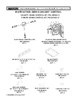
INSTRUCTION, BMR AUXILIARY CONTROL

GRAVITY DOWN CONTROL KIT, P/N 297080-11

POWER DOWN CONTROL KIT, P/N 297080-12

ELECTRICAL CONTROL TEE

P/N 296898-01

QTY. 1

ANGLE, 2” X 2” X 1/8” X 20” LG

P/N 263299

QTY. 1

CAP SCREW

1/4”-20 X 1” LG, GRADE 8

P/N 900004-3

QTY. 4

HEX CAP SCREW

3/8”-16 X 1” LG, GRADE 8

P/N 900014-4

QTY. 2

LOCK NUT, 1/4”-20

P/N 901000

QTY. 8

LOCK NUT, 3/8”-16

P/N 901002

QTY. 2

FLAT WASHER, 3/8”

P/N 902001-2

QTY. 4

WASHER, 1/4” 

P/N 903438-01

QTY. 8

PLASTIC ENCLOSURE WITH

GRAVITY DOWN CONTROL (-11 KIT) OR

POWER DOWN CONTROL (-12 KIT)

QTY. 1

ANGLE PLATE

P/N 263264-01

QTY. 1

Summary of Contents for 297080-11

Page 1: ...N 296898 01 QTY 1 ANGLE 2 X 2 X 1 8 X 20 LG P N 263299 QTY 1 CAP SCREW 1 4 20 X 1 LG GRADE 8 P N 900004 3 QTY 4 HEX CAP SCREW 3 8 16 X 1 LG GRADE 8 P N 900014 4 QTY 2 LOCK NUT 1 4 20 P N 901000 QTY 8...

Page 2: ...STIC ENCLOSURE P N 297210 01 SWITCH MOUNTING BRACKET 2 PLACES P N 297374 01 BUTTON SCREW 1 4 20 X 3 4 LG 4 PLACES P N 900005 3 FLAT WASHER 1 4 8 PLACES P N 902000 2 LOCK NUT 1 4 20 4 PLACES P N 901000...

Page 3: ...ere is no dielectric grease on connector contacts CAUTION Refer to illustrations below for disconnecting checking for dielectric grease and reconnecting locking ring style connectors ALIGN CONNECT FIG...

Page 4: ...r welding on steel parts are contained in the current AWS American Welding Society D1 1 Structural Welding Code Steel Damage to Liftgate and or vehicle and personal injury can result from welds that a...

Page 5: ...LACES CAP SCREW 1 4 20 4 PLACES FLAT WASHER 1 4 8 PLACES PLASTIC ENCLOSURE BOLTING ENCLOSURE TO ANGLE PLATE FIG 5 1 5 Turn OFF the master disconnect switch at the pump box to disconnect battery power...

Page 6: ...8 Connect tee to the control switch cable connector extending from plastic enclosure FIG 6 1 AUXILIARY SWITCH ASSEMBLY RH COLUMN 6 Route the tee Kit item to the RH column FIG 6 1 9 Reconnect battery...

Page 7: ...W UNFOLD 1 2 FIG 7 2B AUXILARY CONTROL FIG 7 2C 10 Push column UP DOWN toggle switch to DOWN position FIG 7 1 to lower platform FIG 7 2A until yellow runner arrow and column decal are aligned FIG 7 2B...

Page 8: ...rol switch as shown in FIG 8 1 Release toggle switch when platform reaches the ground DOWN LOWERING PLATFORM TO GROUND USING AUXILIARY CONTROL SWITCH FIG 8 1 12 To RAISE platform use auxiliary control...

Page 9: ...G 9 1A UP RUNNER ARROW FIG 9 1B 14 Hold both street side control switches 1 and 2 to FOLD platform FIG 9 2 FOLDING PLATFORM USING AUXILIARY CONTROL SWITCH FIG 9 2 FOLD 1 2 13 To stow platform push tog...

Page 10: ...GAGED FIG 10 1B UP PLATFORM STOWED IN UPPER LOCKED POSITION FIG 10 1A 15 Use auxiliary control switch to raise UP platform to upper locking position as follows FIG 10 1A Raise platform until round wed...

Reviews: