


VP30/VP500
MAINTENANCE INFORMATION
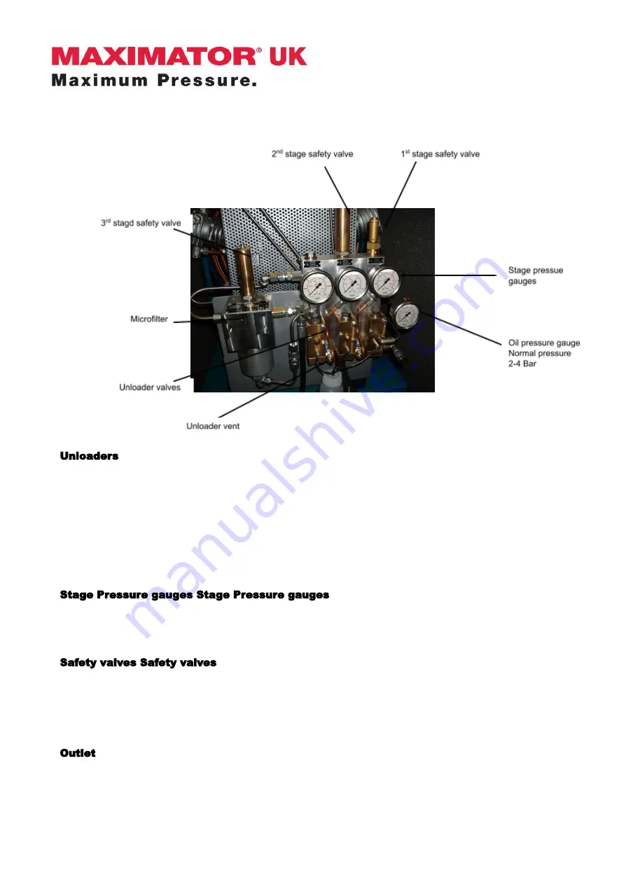
Unloaders
Every time the compressor stops, gas pressure is retained in the cylinders and coolers of each
stage. This gas pressure must be vented to allow the compressor to be started ‘off-load’. The
unloader system is an automatic system for venting this pressure. The system is operated by oil
pressure from the lubrication system, which prevents the gas from each stage from venting to the
unloader vent. Therefore, when the compressor stops and the oil pressure subsides, the unloader
valves will open and the gas will be vented. The Microfilter is also connected to the unloader
system, and its contents, including any condensed oil, will be vented every time the compressor is
stopped.
Stage Pressure gauges Stage Pressure gauges
After each cooler there is a pressure gauge, which shows the gas pressure for each stage when
the compressor is running. The gauges should all reduce to zero after the unloader has vented the
gas from each stage when the compressor stops.
Safety valves Safety valves
After the cooler at each stage is also fitted a safety valve, which prevents each stage from
becoming over pressurised. If a safety valve begins to ‘blow’ (or vent gas to atmosphere), it is
normally a sign that the compressor needs to be serviced.
Outlet
At the compressor outlet, there is a non return valve (check valve). This stops gas from the HP gas
receivers and pipes from venting back through the compressor’s unloader system to atmosphere
when the compressor stops.
July 21
5 of 42
Summary of Contents for VP30
Page 15: ...VP30 VP500 MAINTENANCE INFORMATION Fig 2 Crankcase July 21 15 of 42 ...
Page 17: ...VP30 VP500 MAINTENANCE INFORMATION Fig 3 Crankcase July 21 17 of 42 ...
Page 19: ...VP30 VP500 MAINTENANCE INFORMATION Fig 4 Piston and connecting rod July 21 19 of 42 ...
Page 21: ...VP30 VP500 MAINTENANCE INFORMATION Fig 5 1st Stage Cylinder July 21 21 of 42 ...
Page 23: ...VP30 VP500 MAINTENANCE INFORMATION Fig 6 2nd Stage Cylinder July 21 23 of 42 ...
Page 25: ...VP30 VP500 MAINTENANCE INFORMATION Fig 7 3rd Stage Cylinder July 21 25 of 42 ...
Page 27: ...VP30 VP500 MAINTENANCE INFORMATION Fig 8 Fan and guard July 21 27 of 42 ...
Page 29: ...VP30 VP500 MAINTENANCE INFORMATION Fig 9 Coolers July 21 29 of 42 ...
Page 31: ...VP30 VP500 MAINTENANCE INFORMATION Fig 10 Unloader Manifold July 21 31 of 42 ...
Page 34: ...VP30 VP500 MAINTENANCE INFORMATION Fig 11 Unloaders July 21 34 of 42 ...
Page 36: ...VP30 VP500 MAINTENANCE INFORMATION Fig 12 Oil Lubrication July 21 36 of 42 ...
Page 38: ...VP30 VP500 MAINTENANCE INFORMATION Fig 13 Crankcase Breather July 21 38 of 42 ...
Page 40: ...VP30 VP500 MAINTENANCE INFORMATION Fig 14 Motor July 21 40 of 42 ...