


Evaluates: MAX1455
Room Temperature Bench Test
(MAX1455EVKIT-CS)
The board output is ratiometric to the supply, and there-
fore, a very accurate setting of the supply voltage is
required to minimize measurement errors. Also, the
board contains a Zener diode, which helps protect
against overvoltage and reverse voltage. The protection
circuit enables if the supply becomes less than approx-
imately -0.7V or more than approxi5.6V. The
initial electrical connections should be made as follows:
1) Connect the negative terminal of the power supply
to the 4mm banana socket labeled GND.
2) Connect the positive terminal of the power supply to
the 4mm banana socket l5V.
3) Connect the DVM to the 4mm banana socket
labeled OUT; the ground return should be connect-
ed to the 4mm banana socket labeled GND.
IMPORTANT! To avoid problems with ground loops,
noise, and to prevent possible damage to the
MAX1452KEY adapter, connect all equipment
including the computer (used later) to the same AC
circuit and use one common earth ground
.
If the power supply has a programmable current limit,
set it to approximately 100mA. Adjust the supply volt-
age to +5V and measure the voltage at test point VDD
with respect to test point VSS. At this point, there should
be no connection to the sensor pressure port. Since the
sensor supplied is a gauge type, the output voltage at
the analog connector should read about 0.5V.
Carefully remove the plastic sensor protector (if sup-
plied) and connect a silicone pressure tube to the sen-
sor pressure port.
Grasp the sensor
(not the PCB)
while fitting the tube in place. Perform any required
pressure controller initialization/calibration procedures,
then vent the system. The output voltage should read
0.5V. Perform a few pressure cycles to minimize hys-
teresis effects. Apply full-scale pressure as stated in
the test data or as written on the back of the board, and
confirm that the output reads 4.5V. The user can also
test at other lesser pressures to check for pressure lin-
earity errors.
Extended Temperature Pressure Test
Additional equipment required:
•
Environmental chamber capable of -40°C to +125°C
operation with a noncondensing atmosphere
The unit can now be tested at any temperature in the
-40°C and +125°C range. It is advisable to first perform
one or two full excursions of temperature and pressure
to minimize hysteresis errors. It is recommended that
the electronics be conformal coated in any application
where condensation of moisture might occur. This was
not done to the EV boards, since the user might wish to
modify the circuit for specific requirements.
Since the PCB is not conformal coated, it is important
that the environmental chamber not allow condensation
to take place. If this should happen, a bake-out at
+125°C (with no power applied) for a minimum of 1hr is
recommended. Note that the circuit might behave errat-
ically if moisture is allowed to condense on the PCB
since weak ionic paths affect some high-impedance
nodes on the board.
Most of the errors after compensation are due to the sen-
sor’s drift and nonrepeatable behavior. The EV board
compensation printout includes the raw sensor output that
was measured during compensation at each temperature.
Users might wish to compare this data with their measure-
ments of the sensor output in order to separate sensor
errors from ASIC errors. This can be performed at the sen-
sor connector. To avoid attenuating the sensor output sig-
nal, it is recommended to use a multimeter with an input
impedance greater than 10M
Ω
for this measurement.
Important Note: Download factory-compensated coef-
ficients into a file for future reference before overwrit-
ing flash content.
MAX1455 Evaluation Kit
4
_______________________________________________________________________________________
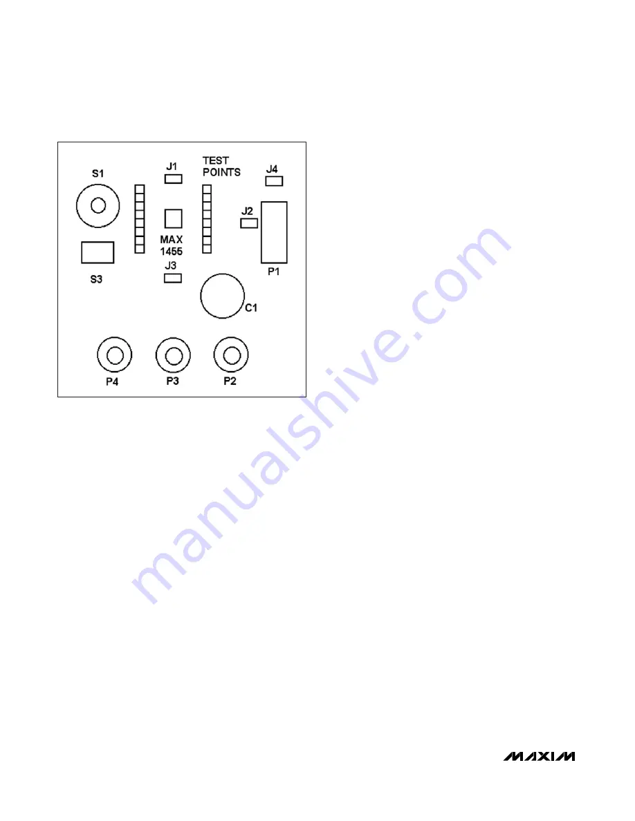
Figure 1. Evaluation (EV) Board Layout