


MAX32600 User’s Guide
System Configuration and Management
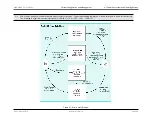
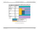
4.1 Power Ecosystem and Operating Modes
After boot/resume for LP0: STOP or LP1: STANDBY, firmware should poll the
register to determine the source of the wakeup event. After
determining the source, firmware should clear the specific
register prior to attempting to enter either LP0: STOP or LP1: STANDBY.
Reference
Wakeup Events from LP0: STOP and LP1: STANDBY
for a more detailed description of this process.
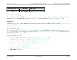
4.1.7.5
Brownout Detector
The Brownout Detector detects a failing power supply and sends a NMI to the ARM processor to shut down the
MAX32600
before losing and/or corrupting core
data. The Brownout Detection monitors the power supply for a
∼
700mV drop and, if detected, sends the NMI to the ARM. The amount of time the supply must be
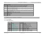
below the detection level is configurable on the
MAX32600
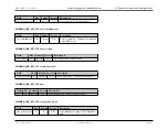
and can be set by firmware as shown in the following
. This setting indicates the minimum window
of detection that the Brownout Detector will see as a brownout.
Brownout Detection Window
Setting
10uS
00b
50uS
01b
250uS
10b
750uS
11b (Default)
Note
The brownout detect flag,
, is disabled by default and does not need to be cleared by firmware on power up;
following any reset condition occurring while the brownout detect flag was enabled, it should be checked to determine if a brownout was detected.
4.1.8
Trickle Charger
When a super capacitor is connected to the V
RTC
rail, the Trickle Charger can be enabled to charge the super capacitor from the main supply (V
DD
) or from the USB
supply (V
USB
). Several charging options are available, including three different charging speeds as well as the optional addition of a series protection diode. Users
can choose from 250 Ohm, 2K Ohm, or 4K Ohm series resistance between the power source voltage and V
RTC
-connected super capacitor. In addition, a series
diode can be enabled between power rails.
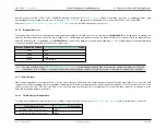
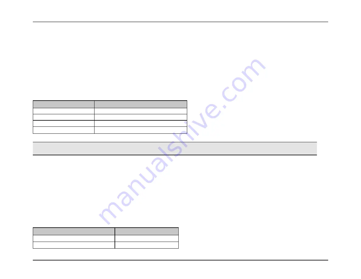
4.1.8.1
Trickle Charger Configuration
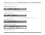
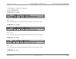
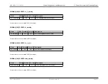
To enable and configure the trickle charger, series resistance, and protection diode, set the
field as shown in the
below.
Trickle Charge Setting
Setting (8-bits)
No Diode, 250 Ohm series resistor
0xA5
No Diode, 2K Ohm series resistor
0xA6
Rev.1.3 April 2015
Maxim Integrated
Page 40