background image

33

MAXDATA Server PLATINUM 1500 IR M6

1.  Observe the safety and ESD precautions.
2.  Turn off all peripheral devices connected to the server. Turn off the server.
3.  Disconnect the AC power cord(s) from the server.
4.  Remove the server’s cover and locate the battery. See the documentation that accompanied 

your server chassis for instructions on removing the server’s cover.

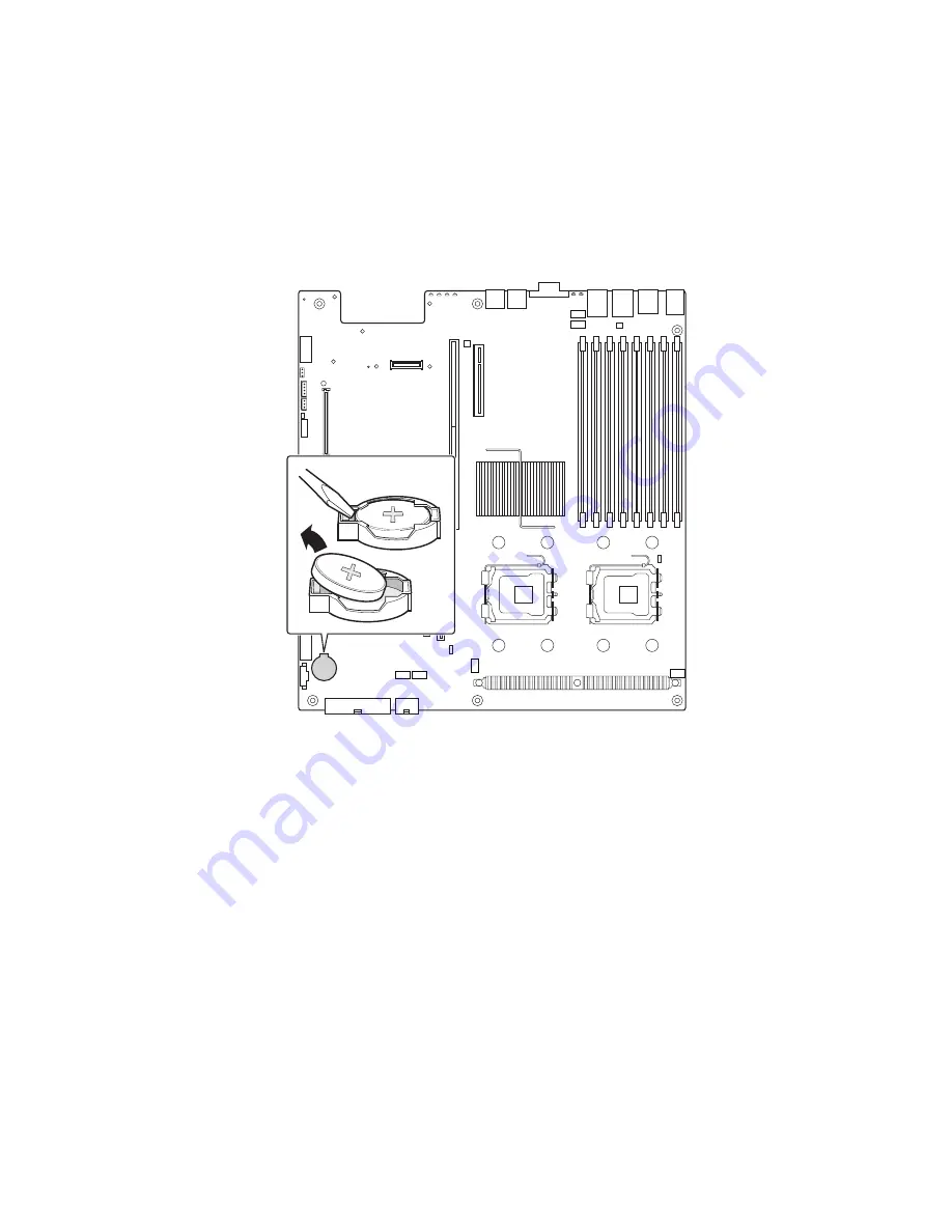
5.  Insert the tip of a small flat bladed screwdriver, or an equivalent, under the tab in the plastic 

retainer. Gently push down on the screwdriver to lift the battery.

6.  Remove the battery from its socket.

Figure 26. Replacing the Backup Battery

7.  Dispose of the battery according to local ordinance.
8.  Remove the new lithium battery from its package, and, being careful to observe the correct 

polarity, insert it in the battery socket.

9.  Close the chassis.
10. Run Setup to restore the configuration settings to the RTC.

Summary of Contents for PLATINUM 1500 IR M5

Page 1: ...User s Manual MAXDATA Server PLATINUM 1500 IR M6 ...

Page 2: ...2 ...

Page 3: ...s 20 4 Hardware Installations and Upgrades 21 Before You Begin 21 Tools and Supplies Needed 21 System References 21 Removing and Installing the Chassis Cover 21 Removing and Installing the Front Bezel 22 Removing the Front Bezel 22 Installing the Front Bezel 22 Installing a SAS or SATA Hot swap Hard Disk Drive 23 Removing a Hot swap Hard Disk Drive 24 Removing and Installing the PCI Riser Assembly...

Page 4: ...pply Specifications 41 600 W Single Power Supply Input Voltages 41 600 W Single Power Supply Output Voltages 41 System Environmental Specifications 41 8 Regulatory and Integration Information 43 Product Regulatory Compliance 43 Product Safety Compliance 43 Product EMC Compliance 43 Product Regulatory Compliance Markings 43 Product RoHS Compliance 43 Installation Precautions 43 Use Only for Intende...

Page 5: ...Drive Carrier 23 17 Attaching a Hot swap Hard Disk Drive to a Drive Carrier 24 18 Removing PCI Riser Assembly from the Server System 25 19 Installing a Full Height Add In Card 26 20 Installing Memory 27 21 Lifting the Processor Socket Handle 28 22 Installing the Processor 28 23 Removing the Socket Cover 29 24 Installing Heat Sink 2U Heat Sink shown 30 25 Changing the Serial Port Configuration 31 2...

Page 6: ...6 ...

Page 7: ...re not trip hazards When you save data to your server s hard disks or to a floppy disk they are stored as magnetic information on the media Make sure that they are not damaged by magnetic or electromagnetic fields Because the electronics in your computer can be damaged by jarring no mechanical devices should be placed on the same surface as the server This is especially important for impact printe...

Page 8: ...nector E Management Network Interface optional L RJ45 serial B port F IO module external connector optional M PS2 keyboard connector G USB 1 connector Table 1 NIC LEDs LED Color LED State Description Left LED Off No network connection Solid Amber Network connection in place Blinking Amber Transmit receive activity Right LED Off 10 Mbps connection if left LED is on or blinking Solid Amber 100 Mbps ...

Page 9: ...ndom blinking green light indicates hard disk drive activity SCSI or SATA No light indicates no hard disk drive activity F System Fault LED Solid green indicates normal operation Blinking green indicates degraded performance Solid amber indicates a critical or non recoverable condition Blinking amber indicates a non critical condition No light indicates POST is running or the system is off G Syste...

Page 10: ...LED Continuous green light indicates the system has power applied to it Blinking green indicates the system is in S1 sleep state No light indicates the power is off is in ACPI S4 or S5 state I Power Sleep button Toggles the system power on off Sleep button for ACPI compatible operating systems J System Status LED Solid green indicates normal operation Blinking green indicates degraded performance ...

Page 11: ...for 10 100 1000 Mb connections Two USB 2 0 ports Internal connections One USB port header which supports two USB 2 0 ports One DH10 Serial A header Six Serial ATA 150 connectors with integrated RAID 0 1 support One ATA 100 44 pin connector for optical drive support SSI compliant 24 pin control panel header SSI compliant 24 pin main power connector supporting the ATX 12V standard on the first 20 pi...

Page 12: ...rt 5 G System Identification LED Blue V System Fan 2 Header JJ SATA SW RAID 5 Activa tion Key Connector H Back Panel I O Ports W CPU Power Connector KK Remote Management Module RMM Connector I Status LED Green Amber X Main Power Connector LL System Recovery Jumpers J Serial B Configuration Jumper Y Battery MM Chassis Intrusion Switch Header K System Fan 4 Header Z Power Supply Manage ment Connecto...

Page 13: ...OS settings will be cleared on the next reset These pins should be jumpered on 1 2 for normal operation Password Clear If pins 2 3 are jumpered administrator and user passwords will be cleared on the next reset These pins should be jumpered on 1 2 for normal operation BMC Force Update Mode If pins 2 3 are jumpered BMC Force Update Mode is enabled These pins should be jumpered on 1 2 for normal ope...

Page 14: ...ED and the 5V standby LED the LEDs turn on amber only if a failure occurs Figure 7 Light Guided Diagnostic LEDs A POST Code LEDs H DIMM C1 Fault B ID LED I DIMM C2 Fault C Status LED J DIMM D1 Fault D DIMM A1 Fault K DIMM D2 Fault E DIMM A2 Fault L CPU 1 Fault F DIMM B1 Fault M CPU 2 Fault G DIMM B2 Fault N 5V Standby 1 A M M I D 2 A M M I D 1 B M M I D 2 B M M I D 1 C M M I D 2 C M M I D 1 D M M ...

Page 15: ...n choose to enable or disable AHCI Mode or Configure SATA as RAID Intel Embedded Server RAID Technology II is enabled by the option Configure SATA as RAID The Intel Embedded Server RAID Technology II feature provides RAID modes 0 1 and 10 For RAID 0 1 and 10 enclosure management is provided through the SATA_SGPIO connector on the server board when a cable is attached between this connector on the ...

Page 16: ...M modules In determining your memory requirements the need for memory sparing or memory mirroring must be considered Memory Sparing and Mirroring The chipset includes hardware that supports memory mirroring and memory on line sparing Both memory mirroring and memory on line sparing provide a way to prevent data loss in case a DIMM fails In a mirrored system the maximum usable memory is one half of...

Page 17: ...mponents Figure 9 Chassis Components A Rack Handles I PCI card bracket low profile B Backplane J Processor air duct C Air baffle K Fan module D Power supply fans L Bridge board E Power supply M Control panel standard control panel shown F Server board N Hard drive bays G PCI card bracket full height O Slimline Optical Drive Bay H PCI add in riser assembly P Front bezel optional A B E C D F H I J K...

Page 18: ...lane acts as a pass through for the SAS SATA data from the drives to the SATA controller on the server board or a SAS SATA controller add in card It provides the physical requirements for the hot swap capabilities The active backplane has a built in SAS controller that does not need communication with the baseboard controller or an add in card Figure 10 Active Backplane Components A Backplane Powe...

Page 19: ...onents A Backplane Power I Fan 3 Power B USB Floppy Connector J Fan 2 Power C SATA 0 K Front Panel Connector D SATA 1 L Fan 1 Power E SATA 2 M Screw F Fan 5 Power N Front Panel USB G Bridge Board Connector O SAS SATA Connectors H Fan 4 Power E D B F A G H L K M J N I O C ...

Page 20: ...ations and hardware for installing hard drives a CD ROM drive or a DVD ROM drive The following figure shows the available options Figure 12 Optional Peripherals A Slimline drive bay B Control panel standard control panel shown C Hard Drive Status LEDs D Hard drive bays A B D C ...

Page 21: ...nsure proper cooling You will need to remove the top cover to add or replace components inside of the chassis Before removing the top cover power down the server and unplug all peripheral devices and the AC power cable NOTE A nonskid surface or a stop behind the chassis may be needed to prevent the chassis from sliding on your work surface 1 Observe the safety and ESD precautions at the beginning ...

Page 22: ...both bezels If you are installing a bezel on your chassis make sure you position it with the control panel area at the top right Removing the Front Bezel 1 Unlock the bezel 2 Pull the bezel out from the chassis Figure 14 Removing the Front Bezel Installing the Front Bezel 1 At each end of the bezel line up the center notch on the bezel with the center guide on the rack handles 2 Push the bezel ont...

Page 23: ...alled hard drive to the drive carrier Two screws are at each side of the retention device or the hard drive Store the plastic retention device for future use Figure 16 Removing the Retention Device from the Hot swap Drive Carrier 5 Remove the hard drive from its wrapper and place it on an antistatic surface 6 Set any jumpers and or switches on the drive according to the drive manufacturer s instru...

Page 24: ...the front of the hard drive carrier 3 Pull out on the black lever to slide the carrier from the chassis 4 Remove the four screws that attach the hard drive to the drive carrier Lift the drive from the carrier Store the drive in an anti static bag 5 If you are not installing a new drive place the plastic retention device into the drive carrier using the four screws you removed from the hard drive 6...

Page 25: ... any installed add in cards 6 Lift up on the two levers on the PCI riser assembly to lift the riser assembly from the chassis See the figure below Figure 18 Removing PCI Riser Assembly from the Server System Installing the PCI Riser Assembly 1 Observe the safety and ESD precautions at the beginning of this book 2 Power down the server and unplug all peripheral devices and the AC power cable 3 Remo...

Page 26: ...tter A 7 Remove the filler panel from the selected add in card slot see letter B 8 Insert add in card until it seats in riser card connector see letter C Figure 19 Installing a Full Height Add In Card 9 Close the retention clip Note Make sure that all empty add in card slots have filler panels installed 10 Install the PCI riser assembly into the server system 11 Install the processor air duct 12 I...

Page 27: ...nd locate the DIMM sockets Figure 20 Installing Memory 5 Make sure the clips at either end of the DIMM socket s are pushed outward to the open position 6 Holding the DIMM by the edges remove it from its anti static package 7 Position the DIMM above the socket Align the small notch in the bottom edge of the DIMM with the key in the socket 8 Insert the bottom edge of the DIMM into the socket 9 When ...

Page 28: ... contact with the metal chassis to dissipate the static charge while handling the processor 2 Avoid moving around unnecessarily Installing the Processor To install a processor follow these instructions 1 Observe the safety and ESD precautions at the beginning of this book 2 Turn off all peripheral devices connected to the server Turn off the server 3 Disconnect the AC power cord from the server 4 ...

Page 29: ... will not be replaced Figure 23 Removing the Socket Cover 9 Lower the CPU load plate and lower the socket lever completely Installing the Heat Sink s 1 The heat sink has Thermal Interface Material TIM located on the bottom of it Use caution when you unpack the heat sink so you do not damage the TIM 2 Set the heat sink over the processor lining up the four captive screws with the four posts surroun...

Page 30: ...d from the server 4 Remove the chassis cover 5 Loosen the four captive screws on the corners of the heat sink 6 Twist the heat sink slightly to break the seal between the heat sink and the processor 7 Lift the heat sink from the processor If it does not pull up easily twist the heat sink again Do not force the heat sink from the processor Doing so could damage the processor 8 Lift the processor le...

Page 31: ...changed Use the following instructions to configure your server board to support DCD signals 1 Observe the safety and ESD precautions at the beginning of this book 2 Turn off all peripheral devices connected to the server Turn off the server 3 Disconnect the AC power cord from the server 4 Remove the server s cover 5 Locate the jumper block for the serial port See figure 25 6 Move the jumper from ...

Page 32: ...NT Danger d explosion en cas de remplacement incorrect de la pile Remplacez la uniquement par une pile du même type ou d un type équivalent recommandé par le fabricant Mettez au rebut les piles usagées en vous conformant aux instructions du fabricant OSTRZEŻENIE Nieprawidłowa wymiana baterii grozi eksplozją Wymieniać tylko na taki sam lub równoważny typ zalecany przez producenta Zużyte baterie uty...

Page 33: ...n removing the server s cover 5 Insert the tip of a small flat bladed screwdriver or an equivalent under the tab in the plastic retainer Gently push down on the screwdriver to lift the battery 6 Remove the battery from its socket Figure 26 Replacing the Backup Battery 7 Dispose of the battery according to local ordinance 8 Remove the new lithium battery from its package and being careful to observ...

Page 34: ...34 ...

Page 35: ...been corrupted you will see other prompts but not the F2 prompt Warning CMOS checksum invalid Warning CMOS time and date not set In this condition the BIOS will load default values for CMOS and attempt to boot IfYou Cannot Access Setup If you are not able to access BIOS Setup you might need to clear the CMOS memory For instructions on clearing the CMOS see Clearing the CMOS Setup Menus Each BIOS S...

Page 36: ...en the selected feature is a submenu or to display a pick list if a selected feature has a value field or to select a sub field for multi valued features like time and date If a pick list is displayed the Enter key will undo the pick list and allow another selection in the parent menu Esc Exit The ESC key provides a mechanism for backing out of any field This key will undo the pressing of the Ente...

Page 37: ...he Password Clear jumper to the Password Clear Protect position covering pins 1 and 2 7 Close the server chassis 8 Reconnect the AC power and power up the server Clearing the CMOS If you are not able to access the BIOS setup screens the CMOS Clear jumper will need to be used to reset the configuration RAM The CMOS Clear jumper is shown in figure 6 1 Power down the system and disconnect the AC powe...

Page 38: ...38 ...

Page 39: ...tion Location LED Color Notes Power Indicates system power is on or off Front control panel Green Off Power is off or in sleep state S5 On Power is on or in sleep stats S0 ID Aid in server iden tification from the back panel Front control panel and board rear left corner Blue Press ID LED button or use Server Management software to turn the LED on and off System Status Visible fault warning Contro...

Page 40: ...in occur to reveal the malfunctioning card 8 Replace or reseat the system video add in card If on board video is bing used the server board may be faulty In addition to the beep codes above additional beep codes are provided if an Remote Management Module is installed The Remote Management Modules provide the following additional beep codes Table 8 Error Beep Codes Provided by Remote Management Mo...

Page 41: ...o not exceed a combined power output of 90 Watts for the 5 V and 3 3 V outputs Exceeding a combined 90 Watts will overload the power subsystem and may cause the power supplies to overheat and malfunction The expansion slots on the server board are rated for no more than 25 Watts for any one slot The average current usage per slot should not exceed 13 Watts System Environmental Specifications Table ...

Page 42: ...42 ...

Page 43: ...C Directive 89 336 EEC European Union Product Regulatory Compliance Markings This product is marked with the following Product Certification Markings Table 11 Product Certification Markings CE Mark Product RoHS Compliance Restriction of Hazardous Substances This server system is compliant to European Directive 2002 95 EC RoHS Installation Precautions Observe all warnings and cautions in the instal...

Page 44: ...tems networks and modems attached to the server before opening it The power supply cord s is are the main disconnect device to AC power The socket outlet s must be near the equipment and readily accessible for disconnection The power supply cord s must be plugged into socket outlet s that is are provided with a suitable earth ground Rack Mount Warnings The equipment rack must be anchored to an unm...

Reviews: