background image

2-1 

FEATURES 


www.maxcessintl.com 

Fife GMA-BL 

MI 2-264 1 B 


Display definitions 

The GMA-BL Actuator Controller uses a QVGA Touchscreen for Operator command inputs 
and status displays. This Control Panel is divided into 5 sections of information for which a 
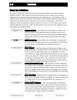
brief description is listed below.  Refer to the Figure 1, for the button locations in the 
standard, horizontal Control Panel. Also refer to the

 GMA-BL Actuator Controller User 

Manual, Figure Sheet 2-265

 for complete display definitions. 

1.


The vertical section on the left side contains the Operation Mode selection buttons 
(Automatic, Servo Center, and Manual) and indicates the current Operation Mode 
selection by displaying the corresponding button in a green color. (Other buttons are 
blue). 

2.


The horizontal section along the top, above the line, contains the status bar which always 
contains the menu number. It may also indicate statuses, errors, and digital I/O. 

3.


The middle section indicates the current Operation Mode, the selected sensor signal level 
in a bar graph, and the level of Guide Point Shift. This section also contains buttons for 
Guide Point Shift and Guide Point Reset. 

4.


The lower middle section contains the Left and Right Jog buttons. 

5.


The vertical section on the right side contains the Sensor Selection and Setup buttons 
and indicates the current Sensor Mode selection by displaying the proper sensor symbol 
in the Sensor Select button. 


Figure 1. 

CONTROL PANEL 

(0° AND 180° ROTATION)


Summary of Contents for Fife GMA-BL

Page 1: ...Fife GMA BL Actuator Controller Quick Start Manual EN MI 2 264 1 B...

Page 2: ......

Page 3: ...ON 1 1 Copyright information 1 1 General information 1 1 Language 1 1 FEATURES 2 1 Display definitions 2 1 Button functions and definitions 2 3 Status bar definitions 2 5 OPERATION 3 1 System setup 3...

Page 4: ...le or in part nor be used for any purpose other than for which disclosed This Instruction Manual is intended to be used in addition to the GMA BL Actuator Controller User Manual Figure Sheet 2 265 Gen...

Page 5: ...the current Operation Mode selection by displaying the corresponding button in a green color Other buttons are blue 2 The horizontal section along the top above the line contains the status bar which...

Page 6: ...ter and Manual and indicates the current Operation Mode selection by displaying that button in a green color 3 The section just below the Operation Mode buttons indicates the current Operation Mode th...

Page 7: ...ucer MANUAL This button initiates the Manual mode No correction is applied to the actuator SENSOR This button is used to select the sensor s to be used for monitoring the web position when the system...

Page 8: ...ARROWS These buttons are used in the menu system to page forward backward when multiple pages of menu choices are available The arrows will appear disabled grayed out when no more choices are availab...

Page 9: ...ENU TIMEOUT The menu screens in the operator interface close automatically after 3 minutes of touch screen inactivity The inactivity timeout option and the timeout value are configurable The clock ico...

Page 10: ...ERROR This error icon appears when the input voltage motor rail voltage or internal 12 volt power is outside acceptable range NETWORK ERROR This icon appears when the operator interface is unable to...

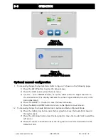
Page 11: ...being used they must be calibrated independently Refer to Figure 3 and Figure 4 shown on the following page 1 Press the SETUP button to enter the Setup menus 2 Press the SENSOR SETUP icon to enter the...

Page 12: ...ion of the buttons 1 Select the desired sensor mode by pressing the SENSOR SELECTION button 2 Press the SETUP button to enter the Setup menus 3 Press the AUTOSETUP icon to enter the AUTOSETUP menu 4 P...

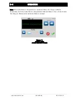
Page 13: ...ssist in the Gain adjustment 4 Press the ACCEPT button to save the new Gain value 5 Press the BACK or HOME button to return to the Operator Level screen 12 To manually change the Guide Point while in...

Page 14: ...he Guide Point is changed while in Automatic Mode the change is effective immediately but if the Guide Point is changed while in Manual Mode or Servo Center modes the change is effective when Automati...

Page 15: ......

Page 16: ...sales maxcess eu www maxcess eu CHINA Tel 86 756 881 9398 Fax 86 756 881 9393 info maxcessintl com cn www maxcessintl com cn INDIA Tel 91 22 27602633 Fax 91 22 27602634 india maxcessintl com www maxc...

Reviews: