MAX power RETRACT R300 Series Manual Download Page 27

MAX POWER 

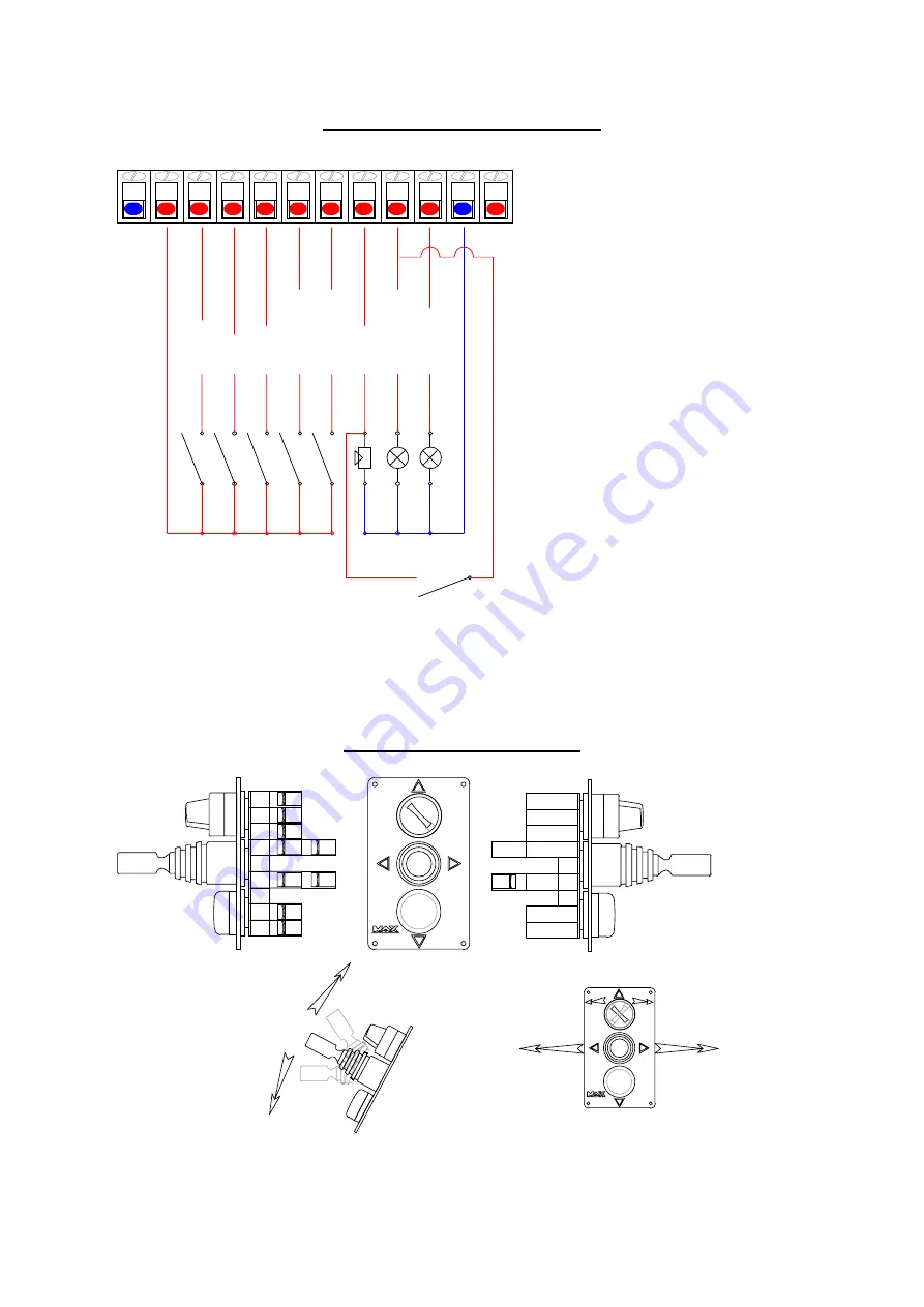
Foot Switch/Custom Control Panel 

ON / OFF

RAISE

LOWER

LEFT THRUST

RIGHT THRUST

ALARM

GREEN LIGHT

RED LIGHT

1

2

12

13

14

15

16

17

18

19

1

2

- + + + + + + + + + - +

All control switches used should be of 

N/O momentary push button type with 
the exception of the on/ off which should 
be of switching type 

Any N/O switches or sensors can be used for 
complementary alarms at will 

Foot switch /custom control panel 


Standard R300 Control Panel 


12

19
1
2

18
17

15

16

13

14

POWER

POWER

Pushing the joy stick up
raises the thruster .

Pushing the joy stick down
lowers  the thruster .

Turning the switch to the
right renders the control
panel active 

Turning the switch to the
left  disables the control
panel

Pushing the joy stick to 
the left moves the yacht
to the left.

Pushing the joy stick to 
the right moves the yacht
to the right

The red turn button illuminates 
when the thruster is up and
locked .

The green light illuminates 

when the thruster is down and
ready to function .


27


INSTALLATION MANUAL RETRACT R 300               


Summary of Contents for RETRACT R300 Series

Page 1: ..._ __ __ __ __ __ _ B BU UI IL LT T B BY Y _ __ __ __ __ __ __ __ __ __ __ __ __ __ __ __ _ D DE EL LI IV VE ER RE ED D _ __ __ __ __ __ __ __ __ __ _ A copy of this manual must remain on board for con...

Page 2: ...CT thruster unit 2 Hydraulic equipment 3 Electrical control system 4 Electrical Power system if fitted with Electro pump CHECK LIST FOR THE PROJECT MANAGER It is very important to carefully read the e...

Page 3: ...allation drawing The following considerations are essential when determining the position of the RETRACT The top of the turbine must be 300 mm below the water line when fully extended In other words t...

Page 4: ...be moulded into the hull during construction or prefabricated and then laminated onto the hull later METAL HULLS The mounting base may be constructed with the hull or prefabricated and then welded on...

Page 5: ...ntil connection to hydraulic system Final installation on the mounting base must be made after thoroughly cleaning and then liberally coating both joining surfaces case and base with a good quality ma...

Page 6: ...son can rotate the eccentric e right or left to raise or lower the locking lever to the position required Replace the bush retaining screw in the nearest convenient hole two holes provided Should the...

Page 7: ...l rules of accessibility to enable periodic checks and maintenance PRESSURE PIPING All hydraulic high pressure power circuit piping must comply with high pressure standards and have a diameter at leas...

Page 8: ...ckpressure on the RD drain line will cause damage to the hydraulic motor The reservoir must be flushed after installation DIRECTIONAL CONTROL VALVE BLOCK The directional control valve DCV must be plac...

Page 9: ...f oil CAUTION Biodegradable and mineral commonly used oils are non compatible and should not be mixed or used together Mixing them will deteriorate certain hydraulic elements If you intend to use a bi...

Page 10: ...ient size see diagram and should be connected directly from the batteries to the fuse main breaker the power relays and finally the EHP There should be no other equipment or connections in the circuit...

Page 11: ...Move joystick to port or starboard and check that the up down hydraulic pump is puling the turbine down AFTER LAUNCHING Check for water leaks Switch on the system power at the breaker and repeat the U...

Page 12: ...O or NF supplied with your system is marked on the valve body and in the control box Adjusting flow limiter 1 Loosen lock nut on bypass flow limiter adjustment screw and open pressure gauge valve both...

Page 13: ...ding on ambient temperature When finished reverse the above operation move the joystick away from yourself forward or up the green light will extinguish the alarm sounds until the red light illuminate...

Page 14: ...nd water pump installation to provide extra oil cooling TROUBLESHOOTING GUIDE PROBLEM Thrust stops almost immediately after it has been applied The alarm buzzer comes on and the green light turns off...

Page 15: ...RETRACT turbine from the DOWN to the UP position Note it can also be used to lower the turbine Lowering the turbine this way has no practical use while at sea but can be useful while on the dry The ma...

Page 16: ...Check and tighten if necessary the plate fixation bolts 4 apply antifouling paint to the closing plate on the outside on the edges and if desired to the plates inner surface If you find growth on the...

Page 17: ...MAX POWER PROJECT MANAGER S TEST RESULTS FORM To be filled out and faxed to MAX POWER 17 INSTALLATION MANUAL RETRACT R 300...

Page 18: ...the hull 2 Is there enough room for general maintenance of the RETRACT and its auxiliary equipment 3 Does the closing plate rest upon a flexible gasket 4 Is the adjustment of the closing plate done i...

Page 19: ...y terminals Volts With the engine s running and the thruster running either direction 1 Record the charging amps of the alternator s Amps 2 Record the voltage at the remote control box Volts 3 Record...

Page 20: ...ue continuously until all stop 3 Up down motor energised 4 Up down up valve opened 5 No position detected 5 Alarm sounds continuously 6 Thruster detected as being up 7 All stop motor valve up down val...

Page 21: ...nimum immersion depth of one full turbine diameter should be respected and the thrusters should be as far forward or aft as possible The thruster must be paralell with the botom of the hull not the wa...

Page 22: ...ruster Fig 1 Fig 2 Gap Caution this situation would cause damage to the turbine while at sea This gap is essential it should be of at least 5mm In this situation there is still up wards movement posib...

Page 23: ...e plastic cam e as on diagram Two holes are avalable in the locking bolt Total fine ajustment allows for 10mm of closing plate movement Initial ajustment must be made using the elongated holes in the...

Page 24: ...MAX POWER Turbine up and locked Turbine down and detected as being down 24 INSTALLATION MANUAL RETRACT R 300...

Page 25: ...g Switch bar C10 The more bars are on the longer the time delay before port 31 32 energisie Switch bar C11 The more bars are on the longer the delay before port 11 swithes on in NO Programing or off i...

Page 26: ...P DOWN PUMP RELAY LEFT THRUST VALVE RIGHT THRUST VALVE PRIME MOVER RELAY NEG NEG NEG BYPASS NEG SUPPLY TO CARD POS SUPPLY TO CARD PRIME MOVER NEG PRIME MOVER POS UP DOWN PUMP SUPPLY POS UP DOWN PUMP S...

Page 27: ...Standard R300 Control Panel 12 19 1 2 18 17 15 16 13 14 POWER POWER Pushing the joy stick up raises the thruster Pushing the joy stick down lowers the thruster Turning the switch to the right renders...

Page 28: ...F ON OFF ON OFF ON OFF ON OFF ON OFF ON OFF ON OFF ON OFF ON OFF Yachts main equipment breaker bord 4 x 2 mm 2 x 1 mm N 17 18 N 31 32 N 1 8 9 11 N N 21 22 N 1 5 6 N 1 3 4 N 1 2 12 13 14 15 16 17 18 19...

Page 29: ...elay 1 Power relay 2 Modle R315 4 Modle R321 4 2 x separate cabling Cable sections A B A B 1m Total length in meters A B 3m A B 5m A B 10m Cable section in mm A B 1m A B 3m A B 5m A B 10m Total length...

Page 30: ...rom hydraulic directional valve to the retract HP thermo plastic hose 1 2 RD Motor drain from retract directly to oil tank LP hose minimum 1 4 or 5 16 RT Return to oil tank from the directional valve...

Page 31: ...sembly Complete up down unit Control box Hydraulic distribution soft start block Control panel Hydraulic oil reservoir with filtration system Hydraulic pump Clutch PTO adapter 1 2 3 4 5 6 7 8 RETRACT...

Page 32: ...own unit Control box Hydraulic distribution soft start block Control panel Hydraulic oil reservoir with filtration system Electro hydraulic pump EHP Power relay power fuses 1 2 3 4 5 6 7 8 24V High po...

Page 33: ...12 4 1 Oil tank 2 Intake strainer 3 Return filter 4 Pump 6 Flow restrictor 8 Bypass 9 Relief valve 10 Pressure guage and valve 11 Directional controle valve 12 Retract motor R300 8 6 33 INSTALLATION...

Page 34: ...er This excludes any damage or faults occurring from normal wear and tear on the following items engine oil seals relay contacts If warranty is registered within the 3 month period following installat...

Reviews: