INSTALLATION MANUAL CT550
8
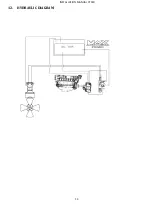
The hydraulic directional control valve (DCV) must be equipped with a pressure gauge and pressure relief
valve and should preferably be placed as close as possible to the thruster unit.
The piping can be flexible or a mix of rigid and flexible type and should have crimp-connected fittings.
The piping should match interior diameters and the service pressure equal or above that which has been
recommended.
The circuits must be as direct as possible and avoid any bends and joints.
The circuits must be clean and closed-off until final connection takes place.
The thruster hoses arriving at the thruster must be of the thermo-plastic non-conductive type.
The hydraulic motor drain line and the return T-line of the DCV should each go separately and directly, back
into the top of the oil tank.
Use synthetic, mineral or vegetable hydraulic oil, to ISO standard 32 to 48
8.
HYDRAULIC SPECIFICATIONS
CT550 Specifications
Power
49 KW
Pressure
250 bar
Flow
125 - 141 lt/min
Detailed instructions and diagrams are delivered with each pack, specific to the installation chosen.
9.
MAINTENANCE
In order to ensure peak performance from your thruster, the tunnel, the leg and the propellers must be kept
clean.
IMPORTANT:
In order to prevent chalky deposits, which cause damage to the oil seals, we recommend
cleaning the shaft and the oil seals first, then applying a layer of silicon oil before assembling the propellers.
ANNUAL BASIS:
CHANGE the anode (if necessary).
CHANGE the gear oil a minimum of every second year. Check the gearoil quality in the gearhouse
every time the boat is out of the water
CHECK the oil and the hydraulic filtration circuit (only if necessary).
EVERY 5 YEARS:
DRAIN hydraulic oil system and change the filter and refill.


