


INSTALLATION MANUAL CT550
4
1.
GENERAL INSTALLATION GUIDLINES
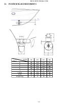
Decide on the best location for the thruster
. (See drawing: “Positioning & Measurements” at back of manual).
The tunnel must be as low as possible and as far forward as possible.
The propellers must not protrude beyond the hull line.
The ideal position of the tunnel is such that there is at least the depth of one tunnel diameter from the water
line to the top of the fitted tunnel. Decreased performance of the thruster due to inadequate immersion depth
can be compensated by fitting the tunnel as far forward as possible (increasing lever arm movement).
Hydraulic thrusters can be fitted vertically, horizontally or tilting.
IMPORTANT:
When using tunnels of different thickness (example: metallic tunnel) it is imperative that the area
between the drive leg/gasket and the motor support, matches the thickness as indicated in the table on the
drawing “Positioning & Measurements” at back of manual and that the motor support is stable.
If you have less than 12 mm thickness, you will require an extra hard rubber gasket between the motor support
and the tunnel.
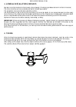
2.
TUNNEL
When the final tunnel position is determined (and all dimensions have been checked), mark the centre of the
tunnel’s position and drill a Ø 10 mm hole. Make up a metal compass from 8 mm rod with 212 mm radius.
Fit compass into the Ø 10 mm holes and trace the form of the tunnel on to the hull (elliptical).
After cutting out the elliptic hole, disc the interior surface of the hull, by approx. 10 to 15 cm around the holes.
The outside surface of the tunnel is then ready to be fibre-glassed.
Do not
stratify over
this zone