background image

2 Before Using This Product


HARS series 

2   Before Using This Product 


2-1   General Information 


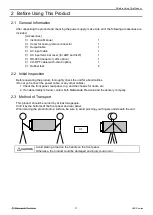
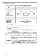
After unpacking the product and checking the power supply, make sure all of the following accessories are 
included. 

[Accessories] 

□ 

Instruction Manual 

□ 

Cover for analog remote connector 

□ 

Output cable 

□ 

AC input cable 

□ 

AC input terminal cover (for 2kW and 3kW) 

□ 

RS-485 Connector (-LRs option) 

□ 

CO-OPT cable (with -LGob option) 

□ 

Rubber feet 


2-2   Initial Inspection 


Before operating the product, thoroughly check the unit for abnormalities. 
(Do not yet connect the power cable, or any other cables.) 

1. Check the front panel, rear panel, top, and the chassis for dents, etc. 
2. If an abnormality is found, contact both Matsusada Precision and the delivery company. 
 

2-3   Method of Transport 


This product should be carried by at least two people. 
Hold it by the bottoms of the front panel and rear panel. 
When placing the product onto a surface, be sure to avoid pinching your fingers underneath the unit. 


Avoid placing a load on the handle on the front panel. 
Otherwise, the product could be damaged and injury could occur. 


or 

Summary of Contents for HARS Series

Page 1: ...Instruction Manual F RA 001 3R3 MODEL HARS series B N 277 9 002 277 9 002 Rev 0 1 ...

Page 2: ...prove its high quality products the information contained in this manual is subject to change without notice Every precaution has been taken in the preparation of this manual Nevertheless Matsusada Precision assumes no responsibility for errors or omissions Neither is any liability assumed for damages resulting from the use of the information contained in this publication Trademarks Company names ...

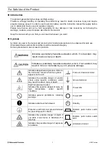
Page 3: ...icates a potentially hazardous situation which if not avoided may result in serious injury or death Indicates a potentially hazardous situation which if not avoided may result in minor or moderate injury or in property damage Indicates danger warning caution Refer to the instruction manual when this symbol appears on the unit Frame or chassis terminal Indicates the possible danger of electric shoc...

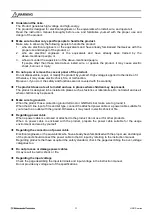
Page 4: ...duct does not suit to install and use in places where children may be present The product is designed to be installed in places such as factories or laboratories Do not install and use it where children may be present Make sure to ground it When the product has a protection ground terminal or GND terminal make sure to ground it When the AC line input of it is an inlet type connect the attached pow...

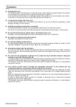
Page 5: ...e the product with the right hand Use only your right hand to operate the product and keep your left hand away from it which can reduce the risk of electric current flowing through the left hand to the vital organs of the body in the event of an electric shock Do not touch the wiring load connected to the output and any terminals connectors during the operation or just after turning output off Ver...

Page 6: ... result in malfunction In that case remove dust immediately Do not block the air inlet and outlet Secure 30 cm space at least around the openings If they are blocked the product cannot show the rated performance due to the internal temperature increase Moreover components deteriorate and it may result in smoke or fire Remove wiring to and from the product when work like welding near it is done Do ...

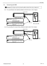
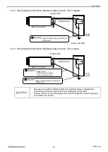
Page 7: ... Shared Interfaces 8 2 6 3 Dimensions 9 3 Connecting 13 3 1 Connecting the AC Input 13 3 1 1 AC input cable connection 500W 1kW 13 3 1 2 AC input cable connection 2kW 3kW 14 3 2 Connecting the GND 15 3 2 1 No grounding for the load frame Models at rated current 1 3A or higher 15 3 2 2 No grounding for the load frame Models at rated current 1 3A or lower 15 3 2 3 Grounding the load frame Models at ...

Page 8: ...1 Setting Interlock Function 31 5 1 12 Setting Power Failure Protection Function 32 5 1 13 Returning to local 33 5 1 14 Adjusting Screen Brightness 34 5 1 15 Touch Calibration 35 5 1 16 System Reset 36 5 1 17 Unit ID Setting 37 5 1 18 Checking LAN Information 38 5 1 19 Delimiter Setting 39 5 1 20 Baudrate setting 40 5 1 21 Interface setting 41 5 2 Sequence Operation Pulse Ramp Sequence 42 5 2 1 Ov...

Page 9: ...Syntax 61 7 6 2 Multiple command 61 7 6 3 Command response 62 7 6 4 Character set of command 62 7 7 Original Command list of Matsusada Precision 63 7 8 Description of Original Command of Matsusada Precision 64 7 9 Range for Voltage Setting and Crrent Setting 69 8 Web Interface 70 8 1 Features of Web Interface 70 8 2 Displaying Web Interface 70 8 3 Home Page 71 8 4 Config Page 72 8 5 Control Page 7...

Page 10: ......

Page 11: ...ssions please contact us 1 2 Overview With 1kW output in a 19 inch rackmouint 1U chassis or 3kW output in 2U the HARS series offers as a high power density as ever had In addition unique high frequency switching technology allows high output and low noise in a compact body 1 3 Features Dial touchscreen for setting voltage current and power from zero to the rated output Automatic crossover switchin...

Page 12: ...60 16 6 1000 HARS 60 33 3 60 33 3 2000 HARS 60 50 60 50 3000 HARS 100 5 100 5 500 HARS 100 10 100 10 1000 HARS 100 20 100 20 2000 HARS 100 30 100 30 3000 HARS 120 4 16 120 4 16 500 HARS 120 8 33 120 8 33 1000 HARS 120 16 6 120 16 6 2000 HARS 120 25 120 25 3000 The output type is described in with P or N P Posituve polarity output N Negative polarity output The voltage current and power that are sh...

Page 13: ...pection Before operating the product thoroughly check the unit for abnormalities Do not yet connect the power cable or any other cables 1 Check the front panel rear panel top and the chassis for dents etc 2 If an abnormality is found contact both Matsusada Precision and the delivery company 2 3 Method of Transport This product should be carried by at least two people Hold it by the bottoms of the ...

Page 14: ...utlet Doing so may cause a short circuit resulting in electric leakage burnout fire or malfunction The product is designed to be installed in a 19 inch rack Use guides to support the chassis when mounting the power supply Avoid supporting the unit only by the installation holes on the front panel The handle on the front panel is used to change the direction the power supply is facing and to pull t...

Page 15: ...terfere with the cooling of the unit and lead to breakdown 2 5 3 Fan Replacement The fan in this power supply has a limited service life As it becomes worn and deteriorates with use its operation might become unstable Note that the service life of the fan will vary greatly depending on the usage environment temperature humidity and dust In order to use this power supply for a long time it is neces...

Page 16: ... OVC IV Devices used at the inlet for equipment 2 Pollution degree Pollution degree 1 No pollution or only dry non conductive pollution No effect due to pollution Pollution degree 2 Only non conductive pollution except for temporary conductivity due to condensation Pollution degree 3 Conductive pollution or dry non conductive pollution that becomes conductive due to expected condensation Pollution...

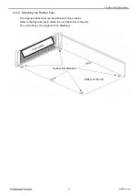
Page 17: ... 2 5 5 Attaching the Rubber Feet The supplied rubber feet can be attached to this product Refer to the figure below to attach the six rubber feet to the unit The unit is heavy Use caution when attaching Bottom of the unit Rubber feet attached ...

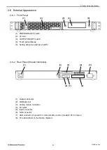
Page 18: ...ch 4 Touch panel display 5 Setting dial also used as a switch 2 6 2 Rear Panel Shared Interfaces 1 Output connector 2 GND terminal 3 Analog remote connector 4 Air outlet 5 Input connector 6 LAN connector 7 USB connector Type B for communication control models 10kV or lower 8 For option Refer to the Option chapter 1 2 3 4 5 1 2 3 4 5 6 7 8 ...

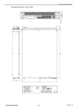
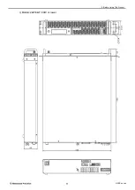
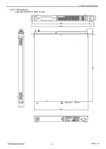
Page 19: ...2 Before Using This Product 9 HARS series 2 6 3 Dimensions a Models 500W 1kW 60kV or lower ...

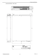
Page 20: ...2 Before Using This Product 10 HARS series b Models 500W 1kW 100kV 120kV ...

Page 21: ...2 Before Using This Product 11 HARS series c Models 2kW 3kW 60kV or lower ...

Page 22: ...2 Before Using This Product 12 HARS series d Models 2kW 3kW 100kV 120kV ...

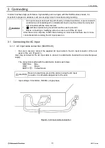
Page 23: ...the AC input After the work is complete confirm that all wiring is correct and that there are no loose connections before turning the AC input power on 3 1 Connecting the AC Input 3 1 1 AC input cable connection 500W 1kW Be sure to securely connect the supplied AC input cable to the AC input connector of the rear panel of the unit Figure1 1 Use crimp terminals for the AC input cable to connect to ...

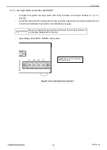
Page 24: ...he cable without crimp terminals attach such as crimp terminals there to connect to a distribution board with a commertial power supply Be sure to electrically ground the product with the AC input terminal It is otherwise dangerous for the user Input voltage 200 240Vac 50 60Hz three phase Figure1 2 AC input terminal connection L1 L3 L2 Attach the cover to the AC input terminal for use ...

Page 25: ... grounding for the load frame Models at rated current 1 3A or lower Rack mount case Ground Output cable GND terminal Load frame Black cable M6 5SQ or more Within about 2 meters Do not use bare wire Class D Class three grounding at single point Rack mount case Ground Output cable GND terminal Load frame 5SQ or more Within about 2 meters Do not use bare wire Class D Class three grounding at single p...

Page 26: ...nding could cause electric shock or damage to the product In case a short circuit or discharge of the load is expected make the ground wire thicker and shorter Rack mount case GND terminal Load frame Output cable Black cable M6 M6 Rack mount case GND terminal Load frame Output cable Load Class D Class three grounding at single point Load 5SQ or more Within about 2 meters Do not use bare wire Class...

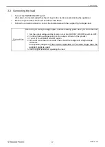
Page 27: ...cable After turing off the high voltage output note the following points when you touch the load 1 Set the output voltage setting to zero or set the OUTPUT ON OFF switch to OFF 2 Confirm that the voltage is zero on the output voltmeter of the product 3 Turn OFF the POWER ON OFF switch 4 Ground it more than 10 seconds Then check the voltage with a high voltage voltmeter It is especially dangerous i...

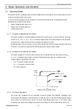
Page 28: ... actually required when using CV mode it is possible to output power while keeping the required output voltage 4 1 2 Constant Current Mode CC Mode The device operates in CC mode when a load current IL is greater than the set output current ISET IL ISET In constant current mode current is constant at the set value ISET whereas load voltage changes depending on the load VSET Constant voltage set val...

Page 29: ...t value Displays the output values of voltageand current ON OFF display Displays the output status ON OFF Key lock button Shifts to the keylock screen Function button Shifts to the function setting screen Monitor button Shifts to the monitor screen 4 3 Status LED Green lighting up Stanby state Blue lighting up When entering the output setting value Blue blinking Output is ready using the external ...

Page 30: ... Touch the Back button on the touch panel display to go back the previous screen Interlock Power failure Return to local Monitor Keylock Ramp Pulse sequence Function Home Menu Mode setting Remote switch Touch calibration Factory reset Backlight System setting LAN Information Unit ID Communication Delimiter Multiset Memory Arc count 1 Preset Set Arc count 2 ...

Page 31: ...wait until the internal temperature of the unit has cooled down and then set the ON OFF switch to ON Internal temperature rise OVER TEMPERATURE Error Output OFF 4 5 2 AC input voltage abnormality protection When the unit does not work correctly because the input voltage becomes lower or unstable ACF will be activated and the output will be cut off When ACF is activated AC FAILURE appears on the to...

Page 32: ...ll be cut off approx 0 1 seconds later after its detection When OCP is activated OVER CURRENT appears on the touch panel display and the output will be cut off In order to clear the state touch the Enter button on the touch panel display or set the external switch to OFF The OVER CURRENT display will disappear and return to the normal screen To restart the output adjust the output current or OVER ...

Page 33: ... Display Item Unlocking OVER VOLTAGE Overvoltage protection Touch the Enter button on the error display OVER CURRENT Overcurrent protection OVER TEMPERATURE Overtemperature protection AC FAILURE AC input voltage abnormality protection INTERLOCK Interlock abnormality ...

Page 34: ...as sometimes electric charge remains in the output after the OUTPUT switch has been turned OFF 5 1 3 Setting Output Voltage and Current Each value can be changed with the Setting change dial by touching the numeric input part voltage current overvoltage protection overcurrent protection voltage limit and current limit on the touch panel display twice or directly touching the set value Any change w...

Page 35: ...key lock function KEY LOCK appears when you press the Keylock button and you can select from Full lock Normal lock or Unlock Under the normal lock or full lock conditions the KeyLock button is locked and Locked appears on the OUTPUT button The lock is canceled if you select Unlock in the locked state Normal With the normal lock operations except Keylock button operation such as voltage current set...

Page 36: ... set value an error will be displayed and the output will be cut off Output OFF As of the limit voltage limit current limit when each setting voltage current value is input the input value is limited by the value set in H Limit To change each set value touch the respective item on the touch panel display On the preset value setting screen not only the protection and limit but also the setting valu...

Page 37: ...e input value is limited by the value set in H Limit If each setting voltage current exceeds the configuration set in H Lmit while the multiset function is enabled the setting value is limited to the H Limit value Note that the output remains on even if the multiset memory number is changed while the output is ON When each setting voltage current value is input while the output is OFF the status L...

Page 38: ... by touching the arc count reset button To enable the function to turn off the output by the arc count touch the arc count button and set it to Enable Touching the arc protec count setting value allows you to set the arc protect count value for the arc you want to turn off the output with the setting change dial When the arc count exceeds the arc protect count setting value the output is turned of...

Page 39: ...the Arc count button and set it to Enable When the arc protect count setting value is touched the protect count value for the arc for which the output is to be turned off can be set with the setting change dial Touch the Arc protection enable time to set the enable time of the arc count to turn off the output with the setting change dial When the arc count exceeds the arc protect count setting val...

Page 40: ...s product is available with the external function of Enable Disable To use the external switch function select Enable To switch the external switch function touch the external switch display Mode setting screen Home screen Menu screen External switch setting screen External switch display ...

Page 41: ...unction This product is available with the interlock function of Enable Disable To use the interlock function select Enable To switch the interlock function touch the interlock display Mode setting screen Home screen Menu screen Interlock display Interlock setting screen ...

Page 42: ...rn ON the output to start If you are not using the power failure protection function set the power failure protection to OFF Disable At the time of power outage recovery or when the POWER ON OFF switch is set to ON the device will return to the state maintained when the input was cut To switch the power failure protection function touch the power failure protection display Mode setting screen Home...

Page 43: ...hen set to REMOTE in addition to returning to local through communication you can also return to local from the touch panel display To return to local touch the Reset to Local button Mode setting screen Home screen Menu screen Return to local button Return to loacl screen ...

Page 44: ...o change the brightness of the screen touch the backlight Level indicator on the touch panel display Use the setting change dial to set the value in the range of 0 minimum to 9 maximum System setting screen Home screen Menu screen Backlight level indicator Backlight setting screen ...

Page 45: ...Touch and a red circle will appear Check the misalignment If you want to readjust the settings touch the Retry button The screen returns to the first screen of the adjustment To cancel the adjustment touch the Cancel button This cancels the adjustment and returns to the previous screen If there is no problem with the adjustment touch OK The adjustment value is saved and the screen returns to the p...

Page 46: ...roduct The product setting is reset to factory defaults Also resetting each setting value clearing the pulse and lamp sequence setting and initializes LAN setting are avialble To execute touch the Factory reset button System setting screen Home screen Menu screen Factory reset button Factory reset screen ...

Page 47: ...17 Unit ID Setting To change theUnit ID touch the Unit ID indicator on the touch panel display Use the setting change dial to set the value in the range of 0 to 31 System setting screen Home screen Menu screen Unit ID indicator Unit ID setting screen ...

Page 48: ... found you need to set them manually after about 30 seconds When each setting value is not yet determined it is displayed in red Afterl the setting value is fixed it is displayed in white To change the setting value touch each item on the touch panel display When the setting value is changed the Apply button is displayed in the lower right corner of the screen When the setting value is changed the...

Page 49: ... Delimiter Setting To change the delimiter touch the Delimiter indicator on the touch panel display Use the setting change dial to set either CR LF CR LF Communication setting screen Home screen Menu screen Delimiter setting screen Delimiter indicator ...

Page 50: ...option is selected In RS 232C RS 485 option and the LGob option you can change the baud rate To change the baud rate touch the baud rate indicator on the touch panel display Use the setting change dial to set one of 9600 19200 38400 bps Communication setting screen Home screen Menu screen Baudrate indicator Baud rate setting screen ...

Page 51: ...nge the interface touch the interface indicator on the touch panel display Use the setting change dial to set one of the following For LRs option 232C 485 Full 485 Half Display Description 232C RS 232C 485 Full RS 485 4 wire transmission full duplex 485 Half RS 485 2 wire transmission half duplex Communication setting screen Home screen Menu screen Interface indicator Interface setting screen ...

Page 52: ...uence function the output for a set ON time as the OUTPUT is turned ON and also stops output for a set OFF time repeating the specified number of times The function can be stopped automatically after the specified number of times or it can be forced to stop by turning the OUTPUT OFF OUTPUT ON OUTPUT OFF ON time OFF time Start pulse sequence Stop pulse sequence 1 cycle Stops after the specified num...

Page 53: ...emory A B and C 0 0s to 99h59m59 9s When multi set memory is enabled the output ON time ON time is not used To change each setting value touch each item on the touch panel display Example Multiset memory is not used OUTPUT ON When the repeat count is 0 ON OFF is infinitely repeated until OUTPUT OFF ON time OFF time 1 cycle If the repeat count is1 end here Example Multiset memory is used together O...

Page 54: ...imultaneously voltage only or currentonly Note The actual output value may differ from the seting due to load and other factors OUTPUT ON OUTPUT OFF ON ramp time OFF ramp time Start ON ramp operation Start OFF ramp operation OUTPUT LED OFF 5 2 5 Ramp Setting Ramp ON time Ramp OFF time Memory ramp time indicator Ramp ON OFF button Ramp mode indicator Function setting screen Home screen Ramp setting...

Page 55: ... the multiset memory A B C 0 0s to 99h59m59 9s When multiset memory is enabled the ramp ON time ON time is not used To change each setting value touch each item on the touch panel display Example In combination with the sequence function Ramp operation in ON OUTPUT ON 1 cycle OUTPUT OFF On time Ramp operation in OFF OFF time Example In combination with Pulse sequence function and Multiset memory R...

Page 56: ...d screws PIN14 10 24V typ output reference voltage 4 2mA MAX PIN15 Output voltage monitor PIN16 NC PIN17 Common PIN8 11 12 13 19 21 24 25 PIN18 NC PIN19 HV status output Current control External Internal switching PIN25 Volatge control External Internal switching PIN24 NC PIN23 NC PIN22 External switch PIN21 NC PIN20 PIN6 NC PIN5 Common PIN1 2 3 14 15 PIN4 NC PIN3 Output current monitor output PIN...

Page 57: ... status LED is blinking blue External Switch operation at power on When the power failure protection function is enabled If the External Switch is opened and the power is turned off in the output ready state status LED flashing blue the power failure protection function will be activated and when the power is turned on again the output ready state will also be canceled status LED lit green To star...

Page 58: ...d the External Switch cannot be used to turn the unit ON OFF Use the OUTPUT ON OFF switch for that TTL LOW OUTPUT ON TTL HIGH OUTPUT OFF or External relay SHORT OUTPUT ON External relay OPEN OUTPUT OFF TTLsignal External relay 13 25 14 1 TB1 External connection 21 17 Internal circuit of unit 470Ω ...

Page 59: ...the switch is open the touch panel display will show an INTERLOCK error message When shorted output is enabled by the OUTPUT ON OFF switch or External Switch When the interlock function is disabled the interlock protection function is not available TTL LOW OUTPUT ON enable TTL HIGH OUTPUT OFF or External relay SHORT OUTPUT ON enable External relay OPEN OUTPUT OFF 13 25 14 1 TB1 TTL signal External...

Page 60: ... frequency power supplies Caution is especially necessary when using the device at high voltage with a floating ground Although this power supply is equipped with complete protection circuits application of excessive voltage or energy may lead to malfunction Setting of Analog remote local control Voltage current configuration is performed by setting to analog remote or local TTL LOW Analog remote ...

Page 61: ...analog remote control See 6 4 Analog Remote Control of Voltage and Current Settings The output voltage can be controlled by external voltage 0 to rated voltage at the input voltage 0 to 10Vdc Fluctuation of external control voltage source will directly affect the boutput voltage Prepare stable voltage source TB1 TTL signal External relay External connection 25 17 13 25 14 1 Internal circuit of uni...

Page 62: ...ted current The recommended input impedance for connected measurement devices etc is at least 1 MΩ Note that when items with input impedance of around 10 kΩ are used the monitor output voltage value drops by approximately 10 on the measurement device Input impedance 10 kΩ Output monitor voltage drops by approximately 10 100 kΩ Output monitor voltage drops approximately 1 Fluctuation of external co...

Page 63: ...or less HV status 19 17 CV status 13 CC status 12 FLT status 11 The contact between output pin and common at time of status output should be shorted CAUTION 17 External connecton 5mA or less Vcc 24V R 4 7kΩ Vcc R Analog remote connector PIN17 PIN11 or 12 or 13 or 19 Common 13 25 14 1 The internal photocoupler is turned on with the status output Internal circuit of unit 22Ω 22Ω 22Ω 22Ω 19 13 12 11 ...

Page 64: ...lt IP address 192 168 010 001 Subnet mask 255 255 255 000 Default gateway 000 000 000 000 Socket number 5025 Home Menu Network LAN information Although the IP address can be set as your desired address make sure not to set the same address as other units The delimiter can be changed on the Web page If you have updated the network settings on the Web screen the updated settings will be reflected by...

Page 65: ...tion formats have the same meaning Long form SOURce VOLTage PROTection number Short form SOUR VOLT PROT number Separate keywords and parameters with a space Case sensitivity SCPI commands are case insensitive Therefore SOUR Sour and sour are all accepted as the same notation Commands Concatenation SCPI commands can be concatenated with a semicolon and can send multiple commands at once Concatenate...

Page 66: ...MAXimum Sets the voltage value Volts PROTection LEVel n MINimum MAXimum Sets OVP value Volts LIMit UPPer IMMediate AMPLitude n MINimum MAXimum Sets Limit voltage value Volts CURRent LEVel IMMediate AMPLitude n MINimum MAXimum Sets the current value Amps PROTection LEVel n MINimum MAXimum Sets OCP value Amps LIMit UPPer IMMediate AMPLitude n MINimum MAXimum Sets Limit current value Amps OUTPut STAT...

Page 67: ... Sets local mode Format SYST LOC Initial value SYST LOC Remarks When this command is received commands except for IDN RST SYST MEASure SYSTem MODe are all ignored SYST REMote Sets remote mode Format SYST REM Initial value SYST LOC Remarks When this command is received all commands will become available SYSTem MODe Gets the unit status Format SYST MODe Query CF CC OVP LD Output state Operational mo...

Page 68: ...marks Regarding the range refer to 7 5 Range for Voltage Setting Current Setting and Power Setting SOURce VOLTage PROTection LEVel n MINimum MAXimum Sets the overvoltage protection value Range 0 to Rated voltage value x 110 Unit kV V mV Format example VOLT PROT 23 45 Initial value VOLT PROT MAX Query In response to VOLT PROT it returns the set overvoltage protection value in actual value Remarks R...

Page 69: ...Query In response to CURR PROT it returns the set overcurrent protection value in actual value Remarks Regarding the range refer to 7 9 Range for Voltage Setting and Current Setting SOURce CURRent LIMit UPPer IMMediate AMPLitude n MINimum MAXimum Sets the upper limit of the current setting value Range 0 to Rated current value Unit A mA uA Format example CURR PROT 23 45 Initial value CURR PROT MAX ...

Page 70: ...nt to 5mA OUTP ON Turns the output on When setting the max and min values describe like below VOLT MAX Sets voltage to the maximum VOLT MIN Sets voltage to the minimum Also to query the set values describe like below VOLT Queries the set voltage value CURR Queries the set current value 7 5 3 Protection Setting SCPI commands are available to set OVP and OCP protection VOLT PROT 100000 Sets the OVP ...

Page 71: ...UNIT number Do not write more than 20 command characters including the delimiter If a large number of setting commands are sent in succession the receive buffer may overflow and not accept the commands In this case please add a wait between each command 7 6 2 Multiple command By using AL for UNIT number the command is sent to all the connected units Syntax example 1 AL CH0 FFFF All the units are s...

Page 72: ...nd CR 0DH characters only as delimiters Command string is not case sensitive Use a space 20H as a separator between unit number command and parameter in the command string table ASCⅡ code 1 SP C O SP L O SP C C CR 23H 31H 20H 43H 4FH 20H 4CH 4FH 20H 43H 43H 0DH 0 H 1 H 2 H 3 H 4 H 5 H 6 H 7 H 0H NUL DLE SP 0 P p 1H SOH DC1 1 A Q a q 2H STX DC2 2 B R b r 3H ETX DC3 3 C S c s 4H EOT DC4 4 D T d t 5H...

Page 73: ...ue Overvoltage OVPSET Set overvoltage protection voltage mode 65 Overcurrent OCPSET Set overcurreSnt protection voltage mode 65 Limit value Voltage OVLSET Set limit voltage voltage mode 66 Current OCLSET Set limit current curret mode 66 Output OUT Set output ON OFF 67 Local remote REN GTL Enable remote control Enable local control 67 67 Measure Output value Voltage VGET Measure output voltage volt...

Page 74: ... Input up to 102 5 of the rated voltage value is allowed use it within the rated value This command is compatible with Multi Command ISET Command Sets the output current value Range 0 to Rated current value Resolution Refer to 7 9 Range for Voltage Setting and Crrent Setting Unit Same as Unit displayed on the front panel Format example ISET 0 02345 For A in unit set 23 45mA Initial value 0 Query I...

Page 75: ... is compatible with Multi Command Note Maximum value of overvoltage protection Rated voltage value 110 OCPSET Command Sets the overcurrent protection value Range 0 to the maximum value of overcurrent protection Resolution Refer to 7 9 Range for Voltage Setting and Crrent Setting Unit Same as Unit displayed on the front panel Format example OCPSET 0 02345 For A in unit set 23 45mA Initial value Max...

Page 76: ... to 102 5 of the rated voltage value is allowed use it within the rated value This command is compatible with Multi Command OCLSET Command Sets the limit current value Range 0 to Rated current value Resolution Refer to 7 9 Range for Voltage Setting and Crrent Setting Unit A Format example OCLSET 0 02345 For A in unit set 23 45mA Initial value Rated current value Query In response to OCLSET the set...

Page 77: ...is received all commands can be used This command is compatible with Multi Command GTL Command Disables remote control Format GTL Initial value GTL Remarks As this command is received all commands other than REN STS and output measurement are ignored This command is compatible with Multi Command VGET Command Monitors the output voltage value Range 0 to Rated voltage value Resolution Refer to 7 9 R...

Page 78: ...mple CO LO CV Output state Local control CV mode CF RM CC OVP Output cutoff Remote control CC mode Overvoltage protection Status Output state Control mode Operational mode Error status Output when an error occurs CF OFF LO Local CC CC mode OVP Overvoltage protection OCP Overcurrent protection CO ON RM Remote CV CV mode OTP Overtemperature protection ACF AC input voltage abnormality Remarks Either ...

Page 79: ...n 2 000 0 0000000 0 0019999 2 000 or more less than 20 00 0 19999 2 000 or more less than 20 00 0 000000 0 019999 20 00 or more less than 200 0 0 199990 20 00 or more less than 200 0 0 00000 0 19999 200 0 or more less than 2000 0 1999900 200 0 or more less than 2000 0 0000 1 9999 2000 or more 0 9999000 2000 or more 0 000 9 999 The maximum value is the result of multiplying each model s rated volta...

Page 80: ... Displaying Web Interface In order to display the information of a unit via the web interface follow the steps below 1 Check the IP address of the unit from Home Network IP information beforehand 2 Input the IP address in the address input field on your web browser and then press the Enter key Enter the address in accordance with your web browser When the TCP IP mode is set to DHCP check the setti...

Page 81: ...8 Web Interface 71 HARS series 8 3 Home Page Click the Home button to display product information LAN communication information and other information ...

Page 82: ...ver Manual IP Address Subnet Mask Default Gateway Set each IP address in TCP IP mode When setting up enter a period as well After changing settings click Apply button Regarding TCP IP Mode Manual IP Address Subnet Mask and Default Gateway changes will not be reflected immediately even clicking the Apply button Click the Apply button to restart the unit Clicking the Cancel button will discard the c...

Page 83: ...s remotely click the Remote control button to switch the display to Remote When Local is displayed on the Remote control button the Output button and Set button are unavailable Output button ON OFF Turn on or off the output of units Set button The output setting of the product is changed Enter the target values to set in the text fields and click the Set button The changing is completed after upda...

Page 84: ...do not want a password leave the field blank Confirm password In the Confirm Password enter the same words as the above new password When the password has been set you must also enter the password to move the screen However this is the function that you use only for screen transmission and it is not a locking function to lock buttons including the output ON OFF button The product remembers the pas...

Page 85: ...the delimiter setting Click the Apply button after selecting one of CR LF CRLF BAUDRATE Change the baud rate of serial communication setting for LRs or LGob option Click the Apply button after selecting one of 9600 bps 19200bps 38400bps UART MODE Change the type of serial communication setting for LRs option Click the Apply button after selecting one of RS232C RS485 ...

Page 86: ...8 Web Interface 76 HARS series 8 8 Links Page By clicking the Links button you can find links of related websites to this product company information of Matsusada Precision Inc ...

Page 87: ...D RxD 3 8 RxD 4 9 RxD 5 10 GND Pin No Signal name 2 RxD 3 TxD 5 GND 4 6 short 7 8 short Item Initial value Remarks Communication speed Asynchronous 9600 bps 9600 bps 19200 bps 38400 bps Data length 8 bits fixed Stop bit 1 bit fixed Parity None fixed Flow control None fixed Delimiter CR 0x0D CR LF CRLF PIN 4 6 and 7 8 are internally shorted Switch to the left No terminator Switch to the right 120Ω ...

Page 88: ...OPT4 25 set the upstream device selector to the right position For communication commands refer to 7 Operating with Digital Control and for communication settings refer to 8 Web Interface Switch status Type of connected device Left CO G32 CO E32 USB OPT LGob option of Matsusada power supplies Right CO OPT2 9 CO OPT2 25 CO OPT4 25 Item Initial value Remarks Communication speed Asynchronous 9600 bps...

Page 89: ...xcessive commands are transmitted Reduce the number of commands or increase the interval between the command transmissions 4 SCPI command does not work Remote mode is not set Send SYST REM to set Remote mode Refer to 7 3 7 4 and 7 5 1 5 Web interface is not displayed Is the IP address of the network set to the default Set the network settings to the default Refer to 7 1 2 10 2 Inquiry If the above...

Page 90: ...e LOCK function activating Refer to 5 1 5 Remote control Is the ON OFF switch turned ON Refer to 5 1 4 Is the external switch setting correct Refer to 6 2 Isn t it in analog remote Refer to 6 4 Isn t it in digital remote Refer to 7 Fuse blows Breaker trips Have you replaced the original screws of the housing with different ones Refer to 2 6 3 The screws may have reached the inside of the product I...

Page 91: ...Revision History Rev No Rev Date Revision Contents 0 0 2021 05 First edition 0 1 2021 07 Corrected some descriptions ...

Page 92: ......
Reviews: