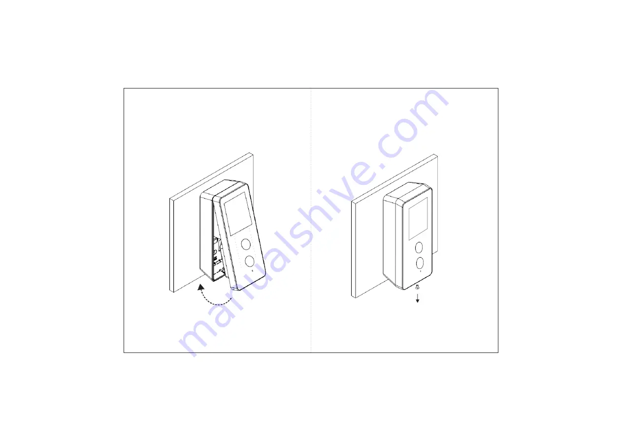
Matrix COSEC ARGO Manual Download Page 7


14


Mounting 

Screw


Step 5: 

Insert the mounting screw into the mounting screw hole 

at the bottom of the device. Tighten the screw to complete the 
Wall Mounting.


13


Step 4: 

Align COSEC ARGO on the mounting plate and hook 

it into the mounting slot. Press the bottom side inwards to lock 
it in place.


Summary of Contents for COSEC ARGO

Page 1: ...servestherighttomakechangesinproduct designandspecificationswithoutpriornotice 29 InstallationInstruction WallMounting 9 InstallationInstruction FlushMounting 15 ConnectingtheCables 21 ConfiguringtheS...

Page 2: ...ariants as follows 1 COSECARGOFACEE 2 COSEC ARGO FACEM 3 COSEC ARGO FACEI Figure 1 Front View Touch Screen Display RGB Camera IR Camera Figure2 BottomView IR LED Mounting Screw Hole Knock Out Area Fig...

Page 3: ...130cm maximum as shown in Figure 6 4 Minimumrecommendeddistanceoftheuser sfacefromthecamera of the device is 30cm while maximum recommended is 120cm as shown in Figure 6 Figure 5 5 Do not install on u...

Page 4: ...ECARGOUnit 2 FlushMountingPlate 3 Wall Mounting Plate 4 Four ScrewsM5 25 5 FourScrewGrips 6 Overswing Diode 7 PowerAdapter 12VDC 2A 8 PowerSupply Cable with DC Jack 9 EM Lock Cable 10 External ReaderC...

Page 5: ...etracedmarkings FixWall Mountingplatewiththesuppliedscrews Tightenthescrewswitha screw driver 9 2 1 Installation Instruction Wall Mounting Step1 PlacetheWall Mountingplateand tracescrewholes1 and2onth...

Page 6: ...he device in non concealed wiring KeepallthecablesparalleltothesideoftheCOSECARGO body in such a way that it should not cover the back portion oftheunitas illustratedinfigure below Radially curve all...

Page 7: ...sertthemountingscrewintothemountingscrewhole atthebottomofthedevice Tightenthescrewtocompletethe Wall Mounting 13 Step4 AlignCOSECARGOonthemountingplateand hook itintothemountingslot Pressthebottomsid...

Page 8: ...D C A B Flush Mounting Template B Figure8 Figure7 A InstallationInstruction FlushMounting Step1 PlacetheFlushMountingTemplateonthedesired installation surface Marktheareaalongthedottedlineandtracethef...

Page 9: ...ll Figure 10 Mounting Slots Cable Connectors Mounting Screwhole KeepallthecablesparalleltothesideoftheCOSECARGO FACE body in such a way that it should not cover the back portion of the unit as illustr...

Page 10: ...ntingscrewintothemountingscrewhole atthebottomofthedevice Tightenthescrewtocompletethe Flush Mounting 19 Figure 12 Step 4 Align COSEC ARGO with the Flush Mounting plate and hookitintothemountingslot P...

Page 11: ...1 White 3 BEEPER Yellow 4 GREENLED Orange 5 GND Black 6 RS 232 RX Pink 7 12V RDR Red 8 RS232 TX Grey 1 GND Black 2 12VDCIN Red Power External Reader Figure 14 Connecting the Cables For Concealed wiri...

Page 12: ...ic ConfiguringtheSettingsfromARGOFACE AssigningIP Server Address toDevice Forfirsttimeuseronly 23 GND Connect the Overswing diode in reverse biased condition paralleltotheEMLockforbetterlifetimecontac...

Page 13: ...ons Figure24 TapSettings Figure23 TapAdmin 25 Ifyouarelogginginforthefirsttime youneedtosetthe PasswordinChooseNewPasswordandconfirmthe same in Confirm New Password Figure22 EnterPassword Figure21 Tap...

Page 14: ...re31 TapAboutDevice Checking the Connectivity Status 27 Figure30 SettheServerConfigurations COSEC VYOM Figure 29 Select Server as VYOM IncaseofCOSECVYOM Figure28 SettheServerConfigurations COSEC CENTR...

Page 15: ...age Open the Web Browser in your computer Enter the IP Address of the COSEC ARGO default http 192 168 50 1 in the address bar of the browser and press the Enter key on your computer keyboard TheLoginp...

Page 16: ...For COSEC VYOM EntertheTenantID forexampleseeFigure37 ClicktheSubmitbutton theWebServerURL Address and Directory Name will be fetched automatically from the Server which cannot be modified see Figure...

Page 17: ...tiveIPStouchscreen with Gorilla glass3 0 Resolution 480x320 pixels HVGA User Capacity 50 000 Communication Port Mobile Broadband Ethernet and WiFi Technical Specification Built In WiFi Yes IEEE 802 11...

Page 18: ...e Warning Thisis aClass A product In a domestic environment this product may causeradiointerferenceinwhichcasetheusermayberequiredtotake adequate measures FCC Certificationin Progress Disposal Of Prod...

Page 19: ...91 1800 258 7747 Email Support MatrixComSec com 37 Website www matrixaccesscontrol com FCC RF Radiation Exposure Statement 1 This Transmitter must not be co located or operating in conjunction with an...

Reviews: