


ENGLISH
LANGUAGE
ENGLISH
LANGUAGE
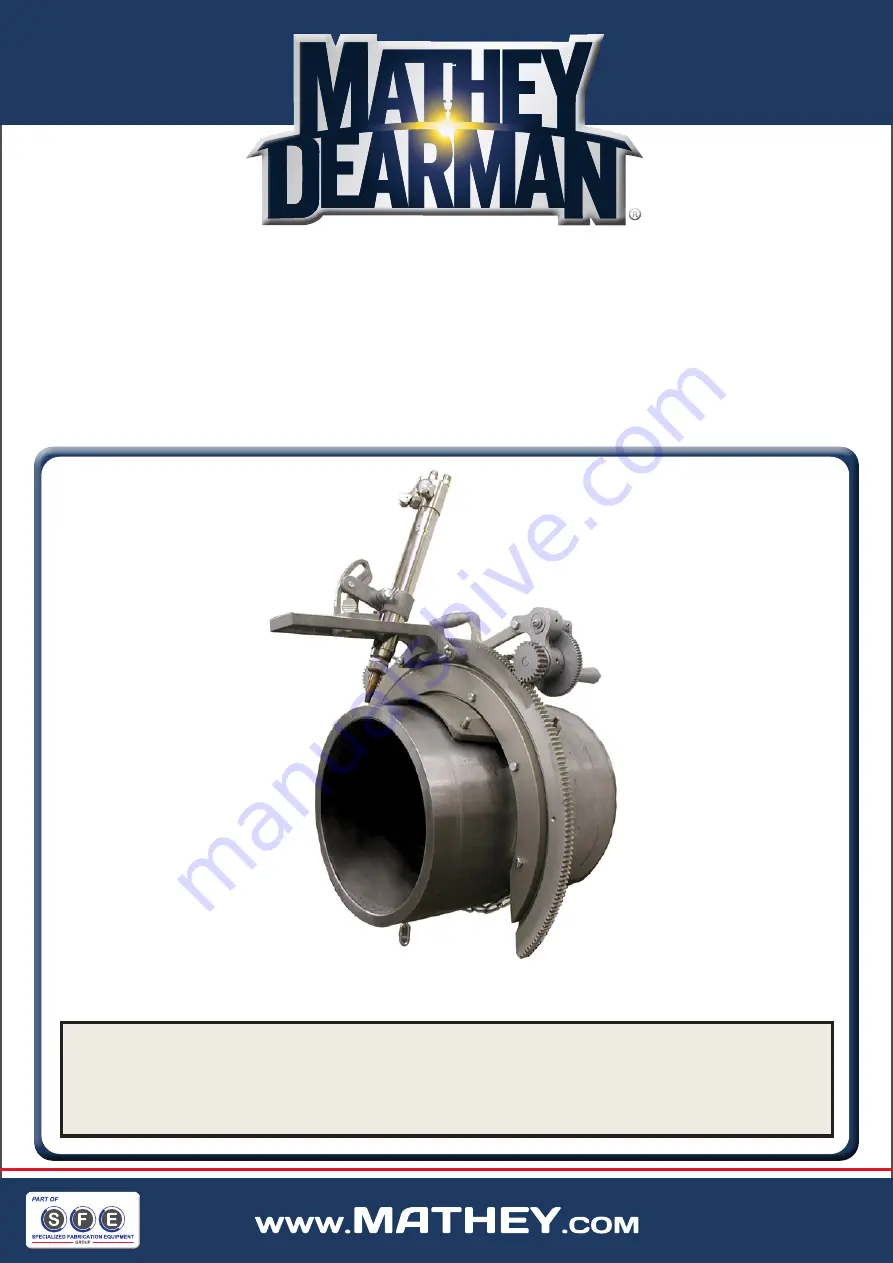
2SA SADDLE MACHINE
PARTS AND OPERATING MANUAL
PART NO: 03-0102-00 / 03-0102-SO1
JUNE 2022
WHERE THERE IS PIPE, THERE’S MATHEY
4344 S. Maybelle Ave, Tulsa, OK 74107 USA
Toll Free: +1 800-725-7311 / +1 918-447-1288
Fax: +1 918-447-0188 / [email protected]
www.mathey.com
2SA Saddle Machine
Parts & Operating Manual
Part Number: 03-0102-000 / 03-0102-S01
REVISED: February 18, 2016
©Mathey Dearman, Inc.
For future reference, record your Saddle Machine model and serial numbers here:
Saddle Machine Model ________
SA
Serial #
M
___________________ Manual ____ Motorized ____


