background image


Operation 


Page 19 


Attention! 
There is an increased risk of accident due to the rotating PTO shaft. 
Do not enter the work area of the PTO shaft when it is rotating. 
For your own safety do not wear any loose clothing, belts, or any other 
loose items. Switch off the implement. Wait until all machine parts have 
come to a standstill before converting or servicing the implement. 


4.3.1. 

Detach the safety chain on both sides. 

4.3.2. 

Press the locking pin on the outer fork and keep it depressed. 

4.3.3. 

Pull the outer fork down from the profile stub of the PTO shaft on the tractor. 

4.3.4. 

Release the locking pin. 

4.3.5. 

Repeat steps 2 to 4 to detach the universal joint shaft on the implement. 

4.4. 

Switching the independent live PTO on and off 

4.4.1. 

Switch-on the independent live PTO - switch on the switch for the front PTO shaft. 
Switch on the independent live PTO at approx. 1000 rpm, and do not increase the 
rpms of the tractor engine when switching on the independent live PTO.  Do not 
switch on the independent live PTO at a speed greater than 1200 rpm. 

4.4.2. 

Switch-off the independent live PTO - switch off the switch for the front PTO shaft. 

4.4.3. 

Never attempt to loosen a seized front implement by switching the independent 
live PTO on and off. 

4.5. 

Run-up time of the front PTO shaft system 

The run-up time of the front PTO shaft system (only necessary if extremely light or ex-
tremely heavy implements will be driven) can be adjusted on the switch-on electronics. If 
the front PTO shaft system will power an extremely light implement, the run-up time must 
be long (rotate the set screw counterclockwise) so that the system switches on less 
abruptly. In the case of powering extremely heavy implements the run-up time should be 
adjusted as short as possible (turn the set screw clockwise) to reduce wear on the cou-
pling. 


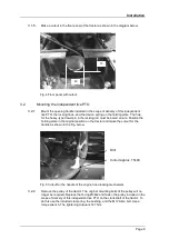
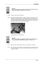
Fig. 27 Switch-on electronics 


Set screw 

Summary of Contents for 131 7122

Page 1: ... 90579 Langenzenn T 49 0 9101 9087 0 F 49 0 9101 9087 20 info matev eu www matev eu Version 04 2011 Original Operating Manual Independent live power take off FPS PTO JD 4020 for John Deere series 4020 2000 U min CCW 2000 U min CW ...

Page 2: ...ndependent live PTO 8 3 3 Installation is complete 16 4 Operation 17 4 1 Coupling and uncoupling implements 17 4 2 Mounting the universal joint shaft 18 4 3 Dismounting the universal joint shaft 18 4 4 Switching the independent live PTO on and off 19 4 5 Run up time of the front PTO shaft system 19 5 Maintenance 20 5 1 Service 20 5 2 Changing the gear oil 20 5 3 Repair 21 6 Disposal 21 7 Warranty ...

Page 3: ...r to important information and handling instructions as needed Listings with bullet points are marked as follows Text Text Text Handling instructions are marked in the sequence in which they should be executed as follows 1 1 1 Text 1 1 2 Text 1 1 3 Text This device is subject to change in the interest of technical progress All information illustrations and technical specifications represent the la...

Page 4: ...ion of personnel Only personnel 18 years of age or older or instructed personnel should install operate and maintain the implements The operator must have read and understood this operat ing manual 2 3 General safety instructions General safety instructions are explained in this section These safety instructions are used in the subsequent sections In addition to the safety aspect you will save mon...

Page 5: ...otating For your own safety do not wear any loose clothing belts or any other loose items Switch off the implement Wait until all machine parts have come to a standstill before converting or servicing the implement Attention Check all threaded unions prior to using the implement and after using the implement Loosened connections must be retightened Damage can occur due to loose connections 2 5 Sup...

Page 6: ...the battery Remove the mounting bolts of the front floor panel including the mounting bolts of the radiator on the floor panel Keep these threaded unions available in a safe place for later use Remove the condenser of the air conditioning system Use coolant R 134 A fill quantity 1 27 kg Attention Injuries can occur due to improper operation The device and the environ ment can be damaged If necessa...

Page 7: ...nd shorten the locking hooks as shown in the Fig below Fig 2 Locking hook Attention Injuries can occur Wear protective work clothing 3 1 4 Make a cutout in the front holding plate of the battery as shown in the diagram be low Fig 3 Cutout in the holding plate Shorten here ...

Page 8: ...te Position the holding plate in the original position on the tractor and make the cutout for the handle as shown in the Fig below Fig 5 Cutout for the handle of the engine hood locking mechanism 3 2 2 Remove the pulley of the tractor The original mounting bolts of the pulley will no longer be required Replace the O ring Ø38x2 and fasten the pulley included in the scope of delivery of this indepen...

Page 9: ...al joint shaft to the pulley with the aid of a torque wrench The tightening torque is 42 Nm Fig 8 Mounting the universal joint shaft to the pulley O ring Ø38x2 Bolt M 12x110 12 9 Pulley Clamp ring Clamping bushing Centering collar to the out side Conical side to the inside Bolts M8x16 12 9 Universal joint shaft Pulley ...

Page 10: ...Mount the gearbox on the matev front lift 131 7142 The tightening torque is 50 Nm Establish the electrical connection Ensure that the hydraulic connection and the electrical connection are not damaged Fig 10 Gearbox on the front power lift 3 2 6 Mount the universal joint shaft on the gearbox using a torque wrench The tightening torque is 42 Nm Gearbox ...

Page 11: ...es for M6 countersunk bolts in the holding plate of the charge air cooler and mount the small oil cooler of the gearbox Connect the hydraulic lines In this process ensure that the lines do not get into the movement zone of the front lift or of the universal joint shaft Fig 12 Mounting the small oil cooler Fig 13 Small oil cooler Gearbox Bolts M8x16 12 9 Small oil cooler Countersunk bolts M6x30 Spa...

Page 12: ...ill plug 3 2 10 Mount the switch on electronics on the cover plate of the universal joint shaft and fasten the sheet metal instead of the battery holder on the tractor Fig 15 Cable with switch on electronics Fig 16 Switch on electronics on the universal joint shaft cover 3 2 11 Connect the extension cable to the plug connection on the switch on electronics ...

Page 13: ...in the cab Remove the cover and connect the switch included with the scope of delivery for this independent live PTO to the cable Fig 18 Switch 3 2 13 Route the brown cable to ground and the red cable to the ignition power 3 2 14 Mount the PTO shaft guard on the gearbox Fig 19 PTO shaft guard Switch ...

Page 14: ...ery on the support Connect the bat tery Use the supplied longer cable Connect the battery to ground at a suitable point Mount the cover and use it to fasten the battery Fig 20 Battery holder in the wheel well Attention If you are mounting the independent live PTO in a tractor that does not have a cab follow the description in sections 3 2 17 and 3 2 18 3 2 17 Mount the battery support element unde...

Page 15: ... 3 2 19 Remove the cross member of the lower attachment hooks from the frontloader and cut an area out of the middle that matches the supplied conversion part Fig 22 Frontloader conversion part 3 2 20 Weld the conversion part onto the cross member in place of the cut out part and paint the weld spot Re assemble the frontloader Fig 23 Cross member reworked for attachment hooks ...

Page 16: ...hing belts or any other loose items Switch off the device Wait until all machine parts have come to a standstill before converting or servicing the implement Attention Injuries due to fluid escaping under high pressure Comply with the instructions in the operating manual 3 3 2 Perform a trial run Switch on the tractor Ensure that the independent live PTO is at a standstill Switch on the independen...

Page 17: ...shaft when it is rotating For your own safety do not wear any loose clothing belts or any other loose items Switch off the device Wait until all machine parts have come to a standstill before converting or servicing the implement 4 1 1 Drive the tractor forward in front of the implement 4 1 2 Lower the front lift 4 1 3 Drive slowly toward the implement until the coupling element of the tractor is ...

Page 18: ...ty do not wear any loose clothing belts or any other loose items Switch off the implement Wait until all machine parts have come to a standstill before converting or servicing the implement 4 2 1 Press the locking pin on the outer fork and keep it depressed 4 2 2 Slide the outer fork onto the profile stub of the front PTO shaft on the gearbox 4 2 3 Release the locking pin 4 2 4 Slightly move the u...

Page 19: ...ch on the independent live PTO at approx 1000 rpm and do not increase the rpms of the tractor engine when switching on the independent live PTO Do not switch on the independent live PTO at a speed greater than 1200 rpm 4 4 2 Switch off the independent live PTO switch off the switch for the front PTO shaft 4 4 3 Never attempt to loosen a seized front implement by switching the independent live PTO ...

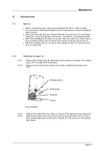
Page 20: ...fill plug If necessary top up with oil After 450 operating hours or every 6 months change the gear oil Clean the oil fil ter in the pump unit 5 2 Changing the gear oil 5 2 1 Remove the oil drain plug and drain the oil into a collection container The oil drain plug is on the underside of the gearbox 5 2 2 Remove the lock ring from the pump unit loosen the M8 bolt and remove the cover Fig 28 Gearbox...

Page 21: ... are faults problems or other indications of malfunction contact your sales con sultant or contact the manufacturer directly matev GmbH Nürnberger Str 50 90579 Langenzenn Tel 49 0 9101 9087 0 www matev eu info matev eu 6 Disposal The device must be disposed of in accordance with the applicable regulations of the mu nicipality or the country Take the parts to the collection points for residual wast...

Page 22: ... 10 Fig 11 Universal joint shaft 11 Fig 12 Mounting the small oil cooler 11 Fig 13 Small oil cooler 11 Fig 14 Gearbox oil fill plug 12 Fig 15 Cable with switch on electronics 12 Fig 16 Switch on electronics on the universal joint shaft cover 12 Fig 17 Extension cable 13 Fig 18 Switch 13 Fig 19 PTO shaft guard 13 Fig 20 Battery holder in the wheel well 14 Fig 21 Electrical connection 15 Fig 22 Fron...

Page 23: ...er matev GmbH Nürnberger Str 50 90579 Langenzenn declares that the machine Independent live PTO Code number 131 7122 and 131 7144 Type John Deere 4520 4720 complies with the provisions of the Machinery Directive 2006 42 EC and with the implementing national statutory provisions The signer is authorized to compile the technical documents The address is the address of the manufacturer Date Signature...

Reviews: