Accessory Checklist
MaxMe Tablet Diagnostic Dongle
OBDII Extension Cable
HDMI Cable Battery Clamps Cable Password Envelope
Cigarette Lighter 5V DC Out Power Adaptor OBDI Converter
(A professional tablet for showing test
results.)
(To connect to an external projector or
monitor with HDMI interface.)
(A piece of paper bearing S/N and
Verification Code, which is required
for your connector activation.)
(To supply power to
via vehicle’s cigarette lighter receptacle.)
non-16pin dongle
(To supply power to MaxMe tablet.)
(To connect the diagnostic dongle
for extension purpose.)
(To provide power to non-16pin
dongle through connection to the
vehicle’s battery.)
(A device for accessing vehicle data.
For detailed non-16pin dongles,
please check the package box.)
Pictures illustrated here are for reference purpose only and this Quick Start Guide is subject to change without notice.
(A converting cable for connecting
non-16 pin dongle.)
Front & Side View
MaxMe Professional Tablet
Rear View
1
Micro USB Port
Mini HDMI Port
Diagnostic Dongle
Diagnostic Dongle Slot
Strap
Screen Lock /
2
Power Button
Front Camera
golo
Button
(For
Instant Messaging
application)
quick access to
(For storing the diagnostic
dongle)
Volume
s
Button
3
Reset Button
Headphone Jack
Micro SD Card Slot
Back Button
4
Charging Indicator
Home Button
Task Switch Button
Microphone
IPS Touch Screen
Camera Flash
Strap
Rear Camera
Audio Speaker
Audio Speaker
Diagnostic Dongle
Diagnostic Dongle Slot
*Notes:
1.
The Micro USB port is used to charge MaxMe tablet.
2.
It enables you to turn the MaxMe tablet on/off with long press, or lock the screen with short
press.
3.
Press it to reset the MaxMe tablet.
4.
Red means Charging, and Green means Fully Charged.
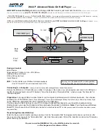
Quick Start Guide
Diagnostic
Dongle
OBD II 16
PIN connector
Communication indicator
Power indicator
Micro USB port
How to install the diagnostic dongle
1. Locate vehicle’s DLC socket: it provides standard 16 pins and is
generally located on driver’s side, about 12 inch away from the
center of dashboard. See Figure
DLC Location
. In case no DLC is
found, please refer to Automobile Repair Manual;
2. Plug the dongle into the vehicle's DLC(It is suggested to use the
OBD II extension cable to connect the DLC and the dongle). For
vehicles with non-16PIN DLC, please choose the desired dongle.
Normally the power indicator of the diagnostic dongle will light up.
NEAR CENTER
OF DASH
Note: Remember to remove the
diagnostic dongle from the DLC
if it keeps unattended.
DLC Location