USERS MANUAL
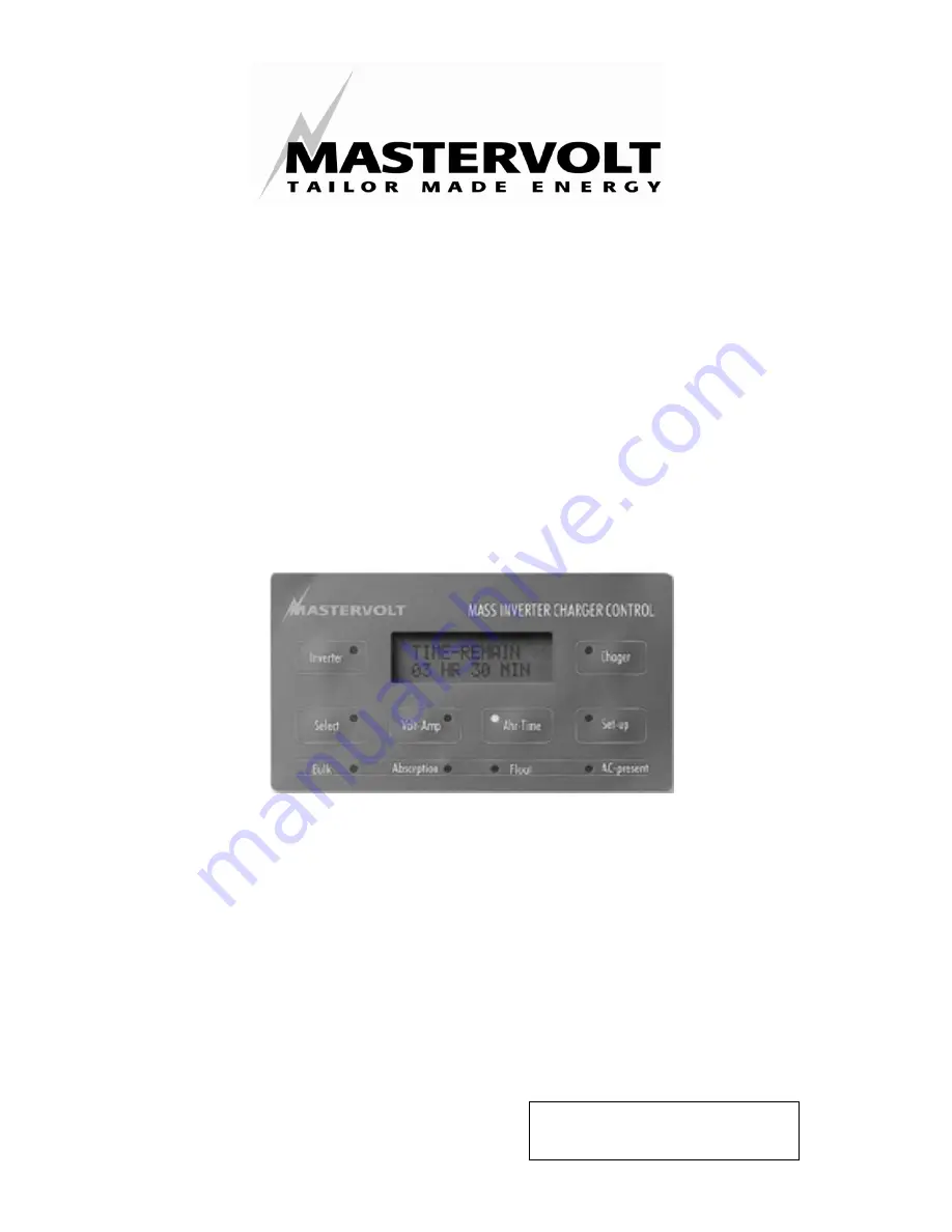
MASTERLINK MICC
MASS INVERTER CHARGER CONTROL
MASTERVOLT Snijdersbergweg 93, 1105 AN Amsterdam The Netherlands Tel.: +31-20-3422100 Fax.: +31-20-6971006
www.mastervolt.com
Language
: English
Version
: V4.0-301104
Page 1: ...ANUAL MASTERLINK MICC MASS INVERTER CHARGER CONTROL MASTERVOLT Snijdersbergweg 93 1105 AN Amsterdam The Netherlands Tel 31 20 3422100 Fax 31 20 6971006 www mastervolt com Language English Version V4 0...
Page 2: ...2 November 2004 Masterlink MICC EN...
Page 3: ...ials needed for installation 7 3 3 Step by Step installation 8 3 4 Installation of an external alarm 10 3 5 Connection of the charger and the inverter 10 4 SYNCHRONISATION AND SETTING THE BATTERY CAPA...
Page 4: ...ting alarm function 26 10 2 Exponent adjustment 26 10 3 Reset menu 27 11 ADDITIONAL INFORMATION 28 11 1 The Peukert Exponent 28 11 2 Time Remaining CEF History 29 12 GENERAL BATTERY INFORMATION 30 13...
Page 5: ...This manual has 16 chapters 1 2 Guarantee Specifications Mastervolt guarantees that this unit has been built in accordance with the legally applicable standards and specifications Should work take pla...
Page 6: ...the Masterlink MICC at locations where there is danger of gas or dust explosion 3 Use other than as mentioned under 2 is not considered to be consistent with the intended purpose MASTERVOLT is not li...
Page 7: ...x0 25 mm shielded twin twisted pair x Or One cable 2x0 25 mm shielded twisted pair and three normal 2 core cables 2x0 25 mm x Two 6 pole modular communication cables RJ12 cross wired see figure 1 to c...
Page 8: ...nk MICC 4 Run the twisted wired cable 2x 0 25 mm between the shunt and the Masterlink MICC Be sure that the wires are long enough to be connected at the left side of the shunt The shunt s output volta...
Page 9: ...the total stand by power consumption will be reduced from 50mA to 30mA if the Mass Combi is switched off by means of the Inverter button on the Masterlink MICC panel When installed it is not possible...
Page 10: ...the Masterlink MICC to the charger or inverter If it is necessary to disconnect batteries and charger inverter then first disconnect Masterlink MICC from the charger inverter For an appropriate operat...
Page 11: ...ry signal n o Chassis ground or Ship s ground in case required Shunt 500A 50mV Minus DC distribution MASS INVERTER CHARGER CONTROL AC present Select Inverter Charger Time remain 03 hr 20 min Float Abs...
Page 12: ...ion LED flashes Press the Ah Time button shortly to display the battery capacity Adjust the required capacity of the main battery by pressing the Set up button If the Select button is held for five se...
Page 13: ...ED is flashing Now press the Set up button shortly to enter the program menu Press the Select button 4 times shortly until the HFC MODE is displayed Select the required setting using the Set up button...
Page 14: ...e major parts remote control of the battery charger remote control of the inverter and retrieving information you re your batteries see figure 6 5 2 Remote control of the battery charger By pressing t...
Page 15: ...ication LED flashes Press the Charger button shortly to display CURRENT CONT Adjust the desired output current 10 100 by pressing the Set up button If the Select button is held for five seconds the ar...
Page 16: ...rter By pressing the Inverter switch the inverter can be switched on and off After a few seconds the Inverter LED illuminates when the inverter is in operation AC output Figure 7 Set up drawing user l...
Page 17: ...rge of the battery This value is automatically compensated by the charge efficiency factor C E F and the Peukert exponent check chapter 11 for more information about the C E F and about the Peukert ex...
Page 18: ...H03 The second level shows the Peukert exponent Standard batteries are rated for a 20 hour discharge This means that a 100 Ah battery can supply 5 amps for 20 hours before a voltage of 1 75 volt cell...
Page 19: ...a battery can handle depends strongly on the type of battery and its quality One cycle is reached if the battery is discharged from 100 state of charge down to 0 followed by a charge up to 100 One cyc...
Page 20: ...n level 1 DEPT 1 Charger Ahr time Volt Amp Inverter Select MICC Installer level Hold select 2 4 sec untill led flashes and select the function below DEPT 7 DEPT 7 A07 Exit level A07 Exit level M03 Set...
Page 21: ...roll through the levels of this menu and adjust several alarm set points For more information see also the set up drawing figure 8 and figure 10 The numbers that are mentioned behind the levels corres...
Page 22: ...attery voltage the alarm will be activated after 30 seconds This prevents the alarm being activated during a small dip in the battery voltage Low battery alarm off setting M03 The fourth level is used...
Page 23: ...our rating and set the MICC according this value For 12 volt systems the capacities of all the installed batteries of the main battery bank can be added If a 24 volt battery system will be used all th...
Page 24: ...easured at the output terminals of the charging system and therefore it is necessary for these voltages to be set approx 0 4 volt lower to compensate for the voltage drop in the wiring In the above me...
Page 25: ...nction on or off The alarm status will still be shown in the display but the external alarm contact of the MICC will not be activated check chapter section for more information about alarm settings If...
Page 26: ...ions Return to users menu M07 By pressing the Select button you can scroll to the EXIT LEVEL If this level is entered you can return to the user menu by means of the Set up button 10 2 Exponent adjust...
Page 27: ...ased by means of the Set up button If the arrow is pointing upwards the set value can be increased Return to users menu A10 If this level is entered you can return to the user menu by means of the Set...
Page 28: ...a high and one at a low discharge rate which are about the minimal and maximal discharge rate for your situation enables you to calculate a value n for the Peukert exponent which fits best to your si...
Page 29: ...aches 1 75 V per cell 10 5V for a 12 V battery This would be equivalent to a discharge rate of 25 A for a 100 Ah battery If the battery delivered 67 134 Ah the appropriate Peukert s exponent would be...
Page 30: ...available However using a generator to charge the battery up to more than 85 is not efficient The reason for this is that the charging current is strongly reduced after reaching 80 85 of the battery...
Page 31: ...tion between battery side and system side chapter 3 3 Back light switches off after 15 seconds Unit in sleep mode Press one of the buttons or refer to chapter 9 step F01 to disable the sleep mode No a...
Page 32: ...ger switched off because of a battery sense error The battery voltage sense wires are connected wrong or the charger has reached the maximum compensation value The charger compensates the voltage loss...
Page 33: ...Measurement 7 35 volts 0 01 volt resolution Amperage Measurement 0 500 Amp 0 2A resolution 0 42A 2A resolution 42 500A Amp Hours Measurement 0 2000 Ah 1 Ah resolution Time remaining 0 255 hours 1 min...
Page 34: ...Panel Minimum required dimensions for installing panel only width x height x depth 120 x 65 x 40mm Grey mounting box Dimensions grey mounting box width x height x depth 140 x 85 x 50mm Dimensions for...
Page 35: ...onformity with the following provisions of the EC EMC directive EMC 89 336 EEG and amendments 92 31 EEC and 93 68 EEC The following harmonized standards have been applied Generic emission standard EN...
Page 36: ...Snijdersbergweg 93 1105 AN Amsterdam The Netherlands Tel 31 20 3422100 Fax 31 20 6971006 Email info mastervolt com...