background image

EXPLODED VIEW

28

AIR

-

POWERED 2

-

IN

-

1 NAILER  058

-

8548

-

4

MC-588548-07

1

2

3

4

5

6

7

8

9

10

11

12

13

14

15

22

24

26

29

30

25

27
28

23

37
38
39

40

16

17

18

12

19

12

20

21

1

31

32 33

34

35

36

41

43
44
45

47

51

50

49

48

53

56 55

57

58

59

60

61

62

63 64

65

66

67

68

69

70

71

72

73

75

74

76

54

52

46

7

42

77

78

24

79

80

81

82

83

84

85

Summary of Contents for AIR-POWERED 2-IN-1 NAILER

Page 1: ...INSTRUCTION MANUAL AIR POWERED 2 IN 1 NAILER 058 8548 4...

Page 2: ...UICK START GUIDE TECHNICAL SPECIFICATIONS 3 SAFETY GUIDELINES 4 9 KEY PARTS DIAGRAM 10 IMPORTANT INFORMATION 11 14 TYPES OF FASTENERS 15 16 OPERATING INSTRUCTIONS 17 22 MAINTENANCE 23 24 TROUBLESHOOTI...

Page 3: ......

Page 4: ...to indicate this information Note The word Note is used to inform the reader of something he she needs to know about the tool PERSONAL SAFETY These precautions are intended for the personal safety of...

Page 5: ...t down after use in the interest of safety and to prevent possible damage to the tool user Keep proper footing at all times in order to ensure correct balance Do not use oxygen or any other combustibl...

Page 6: ...peratures In order to avoid burns or other injuries do not touch the pump the manifold or the transfer tube while the compressor is running Allow the parts to cool down before handling or servicing Ke...

Page 7: ...compressor in a well ventilated area for cooling at a minimum of 12 31 cm away from the nearest wall Protect the air hose and the power cord from damage and puncture Inspect them for weak or worn spot...

Page 8: ...ated Daily lubrication is essential to avoid internal corrosion and possible failures Ensure that the floor is not slippery and wear non slip shoes Floors should be kept clean and clear Always follow...

Page 9: ...is being handed to another person and when it is left unattended Failure to comply may result in moderate injury or damage to equipment Use safety goggles and ear protection Wear safety glasses with s...

Page 10: ...10 AIR POWERED 2 IN 1 NAILER 058 8548 4 No Description No Description 1 Air deflector 5 Safety stand 2 Air inlet plug 6 Release handle 3 Latch 7 Trigger 4 Magazine 8 Depth adjustment dial MC 588548 0...

Page 11: ...ast aluminum body that is strong and light in weight and a rubber made handle sleeve for providing improved control and comfort even during extended use The tool has a 360 air deflector and a safety s...

Page 12: ...25 mm staples 90 PSI 1 25 mm staples 110 PSI 0 6 g cm 3 1 1 2 32 mm brad nails 70 PSI 1 1 2 32 mm brad nails 90 PSI 1 25 mm staples 70 PSI 1 25 mm staples 100 PSI No Description No Description 1 Mast...

Page 13: ...tor be used and be located as close to the tool as possible If a filter regulator lubricator is not installed place up to 6 drops of pneumatic tool oil into the air inlet plug before each use If a fil...

Page 14: ...ble or bottled gas to power this tool Do not use this tool in the presence of any flammable liquids or gases Keep hands and other parts of the body away from the firing head during use Do not point th...

Page 15: ...riety of shank types e g ring smooth spiral and a variety of coatings or nail compositions e g Electro mechanical hot dipped galvanized or stainless steel etc Staples 18 gauge Brad Nails 18 gauge Leng...

Page 16: ...NERS 16 AIR POWERED 2 IN 1 NAILER 058 8548 4 NAIL TYPE ICONS These Icons are used to select the proper nails for this specific nailer Note Icons are colour coded please refer the actual tool for the s...

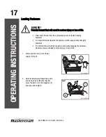
Page 17: ...2 and slide it back fig B DANGER Potential hazard that will result in serious injury or loss of life Disconnect the tool from the compressed air source before loading fasteners Do not point the tool t...

Page 18: ...to the compressor and the other end of the air hose 1 to the tool 2 Use plumber s tape to avoid air leak see section Technical specifications fig D page 12 wood density chart 5 Test the driving depth...

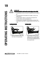
Page 19: ...cause injury to the operators or others apart from damaging the tool Do not load different sized fasteners into the magazine as doing so may cause fasteners to jam Failure to comply could lead to seri...

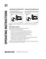
Page 20: ...essive fasteners will fire each time the trigger is pulled Fasteners depth adjustment The Mastercraft Air powered 2 in 1 Nailer has a depth adjustment dial below the trigger to adjust the firing depth...

Page 21: ......

Page 22: ...tool s air inlet Test fire 3 to 5 fasteners into a piece of scrap wood in order to ensure proper operation Note If the fasteners continue to jam please call 1 800 689 9928 WARNING Potential hazard tha...

Page 23: ...IPTION TOOLS OR MATERIALS REQUIRED MAXIMUM SERVICE INTERVAL Each Use or every 2 Hrs Monthly As Needed General inspection free movement Trigger spring safety mechanism None X In depth inspection Worn o...

Page 24: ...ws and caps frequently in order to help prevent personal injury Inspect the trigger springs and safety mechanism for free movement on a regular basis in order to ensure that the safety system is fully...

Page 25: ...tool from the air supply before making any adjustments Repairs must be performed by a qualified service technician only DANGER Potential hazard that will result in serious injury or loss of life If a...

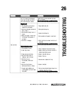
Page 26: ...ective parts 4 Remove adhesive fragment or wood dust 5 Check push lever movement and replace if necessary Have the tool serviced by a qualified technician Output unit piston or driver 1 Air pressure i...

Page 27: ...fire flush into the workpiece 1 The wood is too hard 2 Air pressure is too low 3 Drive blade is worn or broken 4 Incorrect driving depth adjustment 1 Test fire to determine whether nails bend on soft...

Page 28: ...07 1 2 3 4 5 6 7 8 9 10 11 12 13 14 15 22 24 26 29 30 25 27 28 23 37 38 39 40 16 17 18 12 19 12 20 21 1 31 32 33 34 35 36 41 43 44 45 47 51 50 49 48 53 56 55 57 58 59 60 61 62 63 64 65 66 67 68 69 70...

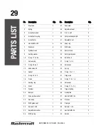
Page 29: ...case 1 10 O ring 17 x 2 65 1 36 Bolt M3 x 8 1 11 Valve spring 1 37 O ring 7 x 1 5 2 12 O ring 33 6 x 2 4 38 Valve case 1 13 Head valve kit 1 39 Spring 1 14 Gasket 1 40 O ring 1 9 x 1 1 2 15 O ring 24...

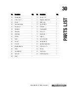
Page 30: ...Flexible bar 1 75 Fixed magazine 1 59 Drive guide 1 76 Pin 3 x17 5 1 60 Safety piece 1 77 Safety plate 1 61 Steel bar 1 78 Trigger II 1 62 Spring 1 79 Self lock bolt M4 1 63 Roll core 1 80 Hex bolt M4...

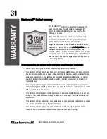
Page 31: ...ted to fuel lubricants vacuum bags blades belts sandpaper bits fluids tune ups or adjustments e This warranty will not apply where damage is caused by repairs made or attempted by others i e persons n...

Page 32: ...ny which shall be covered under the product manufacturer s warranty if any Additional limitations This warranty applies only to the original purchaser and may not be transferred Neither the retailer n...

Reviews: