background image

9

V. Assembly and adjustments
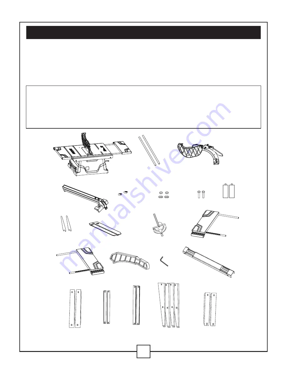
UNPACKING

1.  Carefully remove the table saw from the carton.

2.  Separate the parts.

3.  Lay out all of the parts, and check them against the parts listed below. Examine all of the parts 

     carefully.

WARNING:

• IF

 ANY PART

 IS MISSING OR DAMAGED, DO NO

T

 PLUG IN

 THE TABLE SA

W UNTI


YOU H

A

VE REPLACED


THE MISSING OR DAMAGED 

PARTS. CALL THE T

OL

L

 FREE 

  HELPLINE

 AT

 1-800-689-9928 FOR MORE INFORM

A

TION.

 T

O

 A

VOID INJU

RY, 

THE STYROFOAM BLOCK SHOULD BE REMOVED BETWEEN 


THE MO

T

OR


AND

 THE TABLE.

Table saw assembly

Rear table extension

tubes

Rip fence

Locating seats

Blade

wrenches

Dado table insert

Right table

extension fence

Push sticker

Hex key

Rear table

extension

Long top leg

brackets

Short bottom

leg brackets

Long bottom

leg brackets

Stand legs

Short top leg

brackets

Mitre gauge

Left table

extension fence

Flat washers

and dome nuts

Hex bolts Batteries

Blade guard and

splitter

30

45

60

75

75

90

60

45

30

Summary of Contents for 055-6737-2

Page 1: ...TABLE SAW WITH DUAL EXTENSION WINGS 055 6737 2 User Manual Toll free helpline 1 800 689 9928...

Page 2: ...ance VIII Troubleshooting guide 3 IX Warranty X Part list MOTOR 15 A 120 V 60 Hz MOTOR SPEED 4500 RPM no load MAIN TABLE SIZE 26 x 19 11 16 66 x 50 cm EXTENSION TABLE 6 x 26 15 2 x 66 cm REAR EXTENSIO...

Page 3: ...ctric hobs or cooling appliances 8 Keep other people away from the work area Do not let other people especially children touch the electric power tool or the power cable Keep them away from your work...

Page 4: ...e electric power tool is not in use before maintenance and when exchanging tools such as saw blades drills and mills 20 Do not leave keys in the device Before you switch the device off check that keys...

Page 5: ...maximum possible cutting depth 31 Never cut hands free The workpiece must always lie level on the machine table and be moved along the stop The workpiece must always be pressed hard against the stop...

Page 6: ...ed on or running Danger of cutting yourself 40 Cut workpieces may have sharp edges ridges or wooden splinters Danger of cutting injuries 41 Always switch the machine off and remove the power plug when...

Page 7: ...re Than 0 6 10 12 6 10 12 16 25 7 6 m 18 5 5 m 18 5 5 m 16 4 9 m 14 4 4 m 50 15 2 m 16 4 9 m 16 4 9 m 16 4 9 m 12 3 7 m 100 30 5 m 16 4 9 m 14 4 4 m 14 4 4 m 150 45 7 m 14 4 4 m 12 3 7 m 12 3 7 m Not...

Page 8: ...sion Rip fence Table insert Blade guard Mitre gauge Blade elevation handwheel ON OFF switch with Key Overload reset switch Bevel angle pointer and scale Blade bevel lock knob Mounting holes Splitter K...

Page 9: ...REE HELPLINE AT 1 800 689 9928 FOR MORE INFORMATION TO AVOID INJURY THE STYROFOAM BLOCK SHOULD BE REMOVED BETWEEN THE MOTOR AND THE TABLE Table saw assembly Rear table extension tubes Rip fence Locati...

Page 10: ...8 3 Attach other end of the long top leg bracket to top of another leg using a bolt and nut 4 Attach ong one long bottom leg bracket 7 to the centre of each leg using bolts 3 and nuts 4 This complete...

Page 11: ...Position the stand upside down on the saw base 4 Line up the four holes in saw base and the stand 5 Fasten the saw to stand using four bolts 9 washers 10 and nuts 11 see Fig 1 NOTE Place a washer on...

Page 12: ...ll not be used the saw must be properly secured to a sturdy workbench using the four mounting holes at the base of the saw 2 The surface of the table where the saw is to be mounted must have a hole th...

Page 13: ...Make it a practice to pick up and discard this dust when you have completed cutting BLADE RAISING TILTING HANDWHEEL FIG 5 Attach the blade tilting wheel 1 into the fix pole 3 Assemble the height adju...

Page 14: ...saw blade arbor 4 to its maximum height by turning the blade raising hand wheel counter clockwise see Fig 8 Remove the arbor nut 5 and the outer flange 6 from the saw arbor 3 Place the saw blade on th...

Page 15: ...the handwheel to set the blade to the maximum height and to set the tilt to 0 on the bevel scale Lock the blade bevel locking knob 3 Insert the blade guard assembly 1 into the splitter bracket as show...

Page 16: ...ble 5 Tighten the two clamp bolts 6 Thread the stop screw 1 into the hole of the extension tube 3 7 Install the left hand table side extension the same manner NOTE A For right ripping short workpieces...

Page 17: ...e of the table or on the left side of the table as needed in order to support a long workpiece To adjust the position of the table Extension 1 Loosen the two clamp bolts 5 on the two extension tube br...

Page 18: ...front of the saw table Move the far end of the fence until it is parallel with the mitre gauge groove Push the handle down to lock it and tighten both screws 5 If fence is loose when the handle is in...

Page 19: ...table top tighten the bevel angle locking knob 8 Carefully tighten the adjusting screw 2 until it touches the bevel stop DO NOT OVERTIGHTEN 9 Verify that the blade is still aligned at 90 0 45 Stop 45...

Page 20: ...SERIOUS INJURY AND INABILITY TO MAKE ACCURATE CUTS V Assembly and adjustments continued 20 BLADE TILT POINTER 1 When the blade is positioned at 90 adjust the blade tilt pointer read 0 on the scale 2 L...

Page 21: ...reset button is pushed Overheating may be caused by misaligned parts or by a dull blade Inspect the saw for proper setup before using it again VI Operating instructions BASIC SAW OPERATIONS RAISE THE...

Page 22: ...at the desired distance Lock the table extension clamp bolts 2 3 To adjust fence position loosen lock handles 2 and position auxiliary fence 1 4 Tighten lock handles 2 Before using the table saw poli...

Page 23: ...mately 1 2 5 cm away from the blade 4 Turn the saw ON and allow the blade to come up to full speed 5 Slowly feed the workpiece into the blade by pushing forward only on the section of the workpiece 1...

Page 24: ...bevel angle is set to an angle other than 0 1 It is not safe to rip small pieces It is not safe to put your hands close to the blade In order to ensure your safety rip the small piece from a larger pi...

Page 25: ...of the mitre gauge grooves on the table 2 Adjust the blade height so that it is 1 8 3 2 mm higher than the top of the workpiece 3 Hold the workpiece firmly against the mitre gauge with the blade path...

Page 26: ...right side groove 1 Adjust the blade 1 to the desired angle and then tighten the blade bevel lock knob 2 Tighten the mitre lock handle 3 at 90 3 Hold the workpiece 2 firmly against the face of the mi...

Page 27: ...cutting operations add a wood facing 1 to either side of the rip fence 2 NOTE Before using a wood facing on the rip fence verify that the auxiliary fence is removed 1 Use a smooth straight 3 4 wood b...

Page 28: ...nut 3 5 NOTE Verify that the arbor nut is tight and that at least one thread of the arbor sticks out past the nut 6 After loosing the knob 5 press the device 4 the splitter 6 should be at the lowest p...

Page 29: ...tion Disconnect the table saw from the power source and turn it upside down and then alternately pull upward and downward on the motor unit Observe any movement in the motor mounting mechanism See Fig...

Page 30: ...replaced by a qualified electrician 1 Check the blade with the square and adjust the positive stop 2 Check the blade with the square and adjust the pointer to zero 3 Align the rip fence with the mitr...

Page 31: ...lined in the applicable owner s manual or operating instructions or which is being used for industrial professional commercial or rental purposes c this warranty will not apply to normal wear and tear...

Page 32: ...ages arising in connection with the sale use or inability to use this product This warranty gives you specific legal rights and you may have other rights which may vary from province to province The p...

Page 33: ...her 3 Bolt ST2 9 8 Mitre guide Rip fence Hex bolt M14 Extension table left Extension pole left Scale extension pole left Scale for extension pole left Table insert Washer Main table Rear extension pol...

Page 34: ...Hex bolt M8 40 Washer 8 Hex nut M8 Case Bolt ST4 2 16 Press wire block Cord inlet Plug cord 135 136 137 138 139 140 141 142 143 144 145 146 147 148 149 150 151 152 153 154 155 156 157 158 159 160 161...

Page 35: ...16 Gear cover Bearing 6003 2Z Ring for shaft or hole 35 Output shaft Half round key 5 6 5 16 193 194 195 196 197 1 1 1 2 1 Gear Ring for shaft 16 Self lubricating bearing Blade wrench Hex key Descrip...

Page 36: ...106 107 108 109 110 111 4 104 112 46 113 114 12 115 116 117 118 119 120 117 115 113 112 121 122 123 124 125 126 127 128 129 130 129 128 129 128 129 128 127 127 127 131 132 133 134 135 135 136 137 138...

Reviews: