headline bars
continuation tabs
notes
warnings
17
headline bars
continuation tabs
notes
warnings
model no. 054-8106-4 | contact us 1-800-689-9928
16
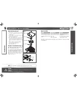
REPLACING THE BLADE
(fig 5)
1. Unplug the biscuit joiner from the power supply.
2. Loosen the 4 screws with a screwdriver to open
the blade cover.
3. Press the spindle-lock button and loosen the outer
flange using the blade wrench.
4. Place a new cutting blade on the spindle, taking
care that direction of rotation indicated on the
blade corresponds with the arrow indicator on the
tool.
5. Press the spindle-lock button and tighten the
outer flange with the blade wrench.
6. Reinstall the blade cover.
REPLACING THE CARBON BRUSHES
(fig 6)
Both carbon brushes should be replaced at the same
time. Use only identical carbon brushes.
Use a screwdriver to loosen the screw and remove
the cover. Release the spring, take out the worn
carbon brushes and insert the new ones. Reset the
spring to fix the carbon brush and secure the cover.
Make sure the groove on the carbon brush points
towards outside of the tool.
TROUBLESHOOTING
Problem
Possible Causes
Solution
The biscuit joiner does not start Not connected to power source
Plug the biscuit joiner into a
power source
The blade binds or smokes from
friction
Blade is dull
Replace with a new sharp blade
Blade is on backwards
Install the blade correctly
If the problem remains unsolved after performing the checks described above, call the toll-free helpline
at 1-800-689-9928.
MAINTENANCE
TROUBLESHOO
TING
NOTE:
Always check the depth of cutting after replacing the blade. Readjust it if necessary.
WARNING!
• Make sure that the rotation direction on the blade corresponds with the indicator on the tool.
CAUTION!
• The flat surface of the outer flange must point outwards.
FPO
fig 5
Outer flange
Inner flange
Cutting blade
Blade cover
fig 6
Cover
Carbon brush

