


16
114716
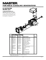
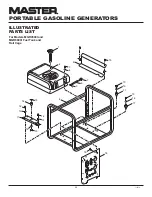
PORTABLE GASOLINE GENERATORS
R
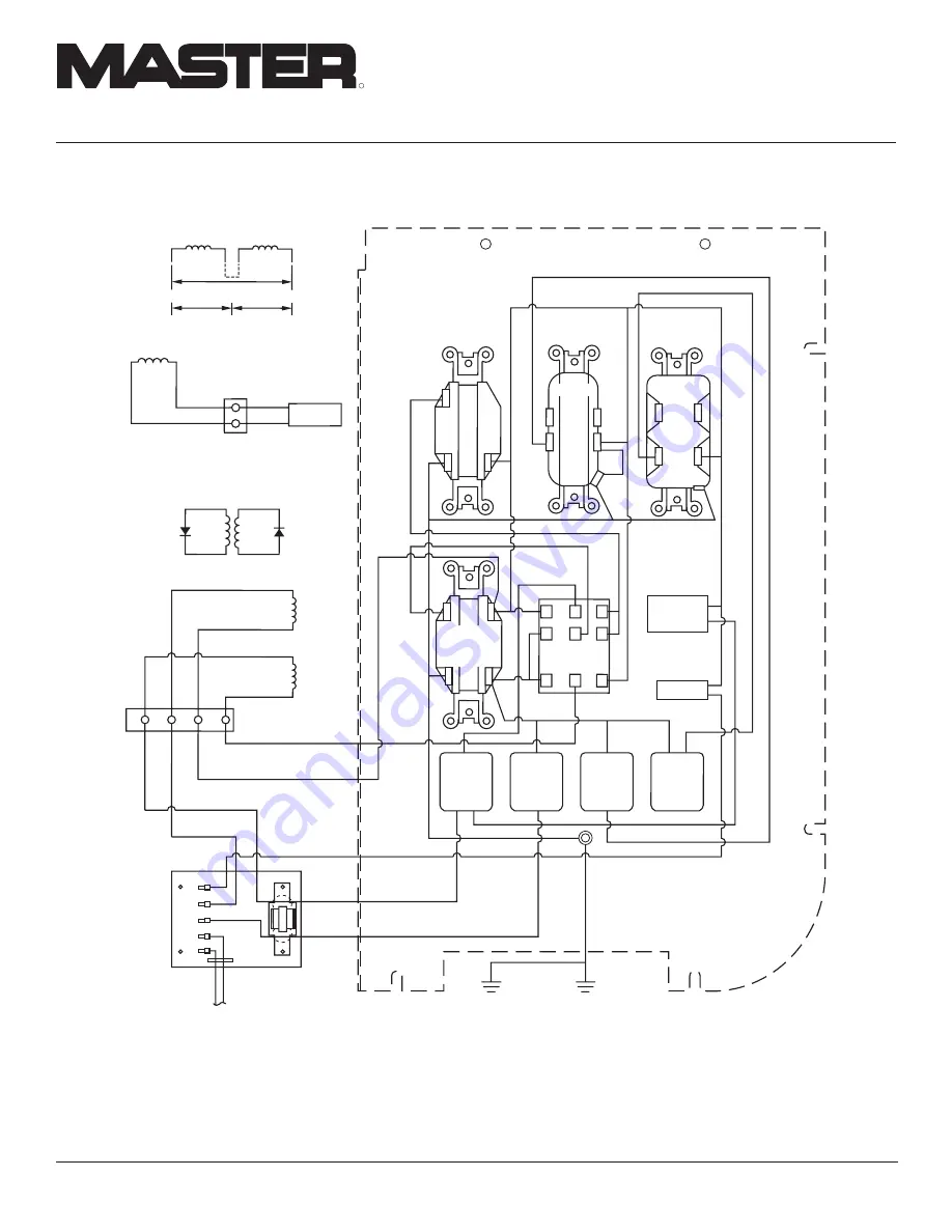
WIRING DIAGRAMS
Continued
Figure 21 - Wiring Diagram, Models MGR4500I and MGR6000I
GFCI
LINE
W
H
ITE
HOT
Duplex
Circuit
Breaker
20A
Circuit
Breaker
20A
Circuit
Breaker
25A/30A
Circuit
Breaker
25A/30A
Hour
Meter
Full Pwr
Selector
Switch
T2
s
1
s
2
Red
Yellow
Green/Yellow
Green/Yellow
Grn/
Ylw
Grn/
Ylw
Grn/
Ylw
Green/
Yellow
Green/
Yellow
To Alternator
Ground
To Solenoid
Green/
Yellow
To Roll Cage
Yellow
White
White
Blue
Red
Black
Black
Black
Blk
Blk
Black
Black
Black
Red
Red
Red
Red
Red
Green
120/240V
20A/30A
Receptacle
120V, 30A
Receptacle
120V, 15A
Receptacle
120V, 20A
Receptacle
White
White
Wht
Wht
Wht
Wht
Wht
White
White
White
White
Auto-Idle
Stator
110/120V
T1
T2
T3
T4
L2
L1
110/120V
220/240V
Rotor
Auxiliary
Phase
Diode
Diode
Stator
White
Brown
Capacitor
White
White
T2
Green
Red
Black
Blue
Main
Windings
T1
T3
T4
T1
T2
T3
T4


