background image

11 


ASSEMBLY INSTRUCTIONS                                                                                                                 


8. Flip assembly upright. Place drip tray 
assembly (E) onto the left drip tray rail (O) and 
right drip tray rail (T). Then, slide the grease 
cup (F) into the slot on the underside of the 
drip tray assembly (E). 


7. Carefully flip the assembly upside down. 
Using the wrench provided in the pack of 
unlockable casters (Z), install the unlockable 
casters (Z) to the front legs of the assembly. 
Then, install the lockable casters (W) to the 
rear legs of the assembly. 


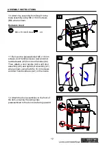
9.1. Remove the preassembled M6 x 20 
screws, spring washers, flat gaskets and lid 
handle bezels (D) from lid handle (C). Then, 
attach lid handle (C) to lid assembly (A) where 
shown with the flat gaskets, spring washers 
and M6 x 20 mm screws on the inside. 
9.2. Remove the preassembled flat gasket 
and wing nut from the temperature gauge (B). 
Then, attach temperature gauge (B) to lid 
assembly (A) where shown using the flat 
gasket and wing nut on the inside. 
9.3. Insert knobs (J) where shown on lid 
assembly (A) by simply pressing them into 
each valve. 


Summary of Contents for 0699961

Page 1: ...uids in the vicinity of this or any other appliance 2 An LP tank not connected for use should not be stored in the vicinity of this or any other appliance DANGER If you smell gas 1 Shut off gas to the appliance 2 Extinguish any open flames 3 Open the lid 4 If the odor continues keep away from the appliance and immediately call your gas supplier or fire department WARNING For Outdoor Use Only ATTAC...

Page 2: ...ER If you smell gas 1 Shut off gas to the appliance 2 Extinguish any open flame 3 Open lid 4 If odor continues keep away from the appliance and immediately call your gas supplier or your fire department Always read and understand the WARNINGS and INSTRUCTIONS that are contained in this manual before attempting to use this grill to prevent possible bodily injury or property damage Always keep this ...

Page 3: ...NTENTS Safety Information 4 Package Contents 6 Hardware Contents 8 Assembly Instructions 9 Operating Instructions 15 Care and Maintenance 23 Troubleshooting 24 Warranty 26 Exploded View 27 Replacement Parts List 28 ...

Page 4: ...ve abrasion or wear or cuts that may affect safe operation of the grill If there is evidence of excessive abrasion or wear or the hose is cut it must be replaced prior to the grill being put into operation The replacement hose assembly must be one specified by the manufacturer 7 Keep your grill in an area clear and free from combustible materials gasoline and other flammable vapors and liquids 8 D...

Page 5: ...er and birth defects or other reproductive harm Wash your hands after handling this product 23 Chemicals known to the state of California to cause cancer and birth defects or other reproductive harm are created by combustion of propane IMPORTANT We urge you to read this manual carefully and follow the recommendations enclosed This will ensure you receive the most enjoyable and trouble free operati...

Page 6: ...6 PACKAGE CONTENTS 俄 C D J E G I H F A K L M N P O R Q O S T U V W X Y Z A1 A2 A3 A4 A5 B ...

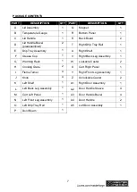
Page 7: ...ht Shelf 1 F Grease Cup 1 V Right Back Leg Assembly 1 G Warming Rack 1 W Lockable Caster 2 H Cooking Grate 2 X Cart Right Panel 1 I Flame Tamer 4 Y Right Front Leg Assembly 1 J Knob 4 Z Unlockable Caster 2 K Left Shelf 1 A1 Right Door Assembly 1 L Left Back Leg Assembly 1 A2 Door Handle Sleeve 4 M Cart Left Panel 1 A3 Door Handle Bezel 4 N Left Front Leg Assembly 1 A4 Door Handle 2 O Left Drip Tra...

Page 8: ...ith package contents list and hardware contents list If any part is missing or damaged do not attempt to assemble the product Estimated Assembly Time 60 minutes with recommended 2 people Tools Required for Assembly Phillips screwdriver not included wrench included AA BB M4 x 8 mm Screw Qty 20 M6 x 16 mm Screw Qty 30 ...

Page 9: ...o cart left panel M as shown using M4 x 8 mm screws AA Hardware Used AA 3 Remove screws and nuts preassembled to magnet Q then attach magnet Q to bottom panel R as shown using the previously removed hardware R Q 3 AA AA T V Y X 2 2 Attach right back leg assembly V right front leg assembly Y and right drip tray rail T to cart right panel X as shown using M4 x 8 mm screws AA Hardware Used M4 x 8 mm ...

Page 10: ...x 8 AA AA P 6 AA BB S 5 5 Attach back board S between the left and right side of the assembly using M6 x 16 mm screws BB where shown Hardware Used M6 x 16 mm Screw X 6 AA M4X8mm Screw x 10 BB 4 Attach the assembly from Step 1 and the assembly from Step 2 to the bottom panel R where shown using M6 x 16 mm screws BB Hardware Used M6 x 16 mm Screw X 6 AA M4X8mm Screw x 6 BB RF LF BB 4 ...

Page 11: ... Then install the lockable casters W to the rear legs of the assembly 9 1 Remove the preassembled M6 x 20 screws spring washers flat gaskets and lid handle bezels D from lid handle C Then attach lid handle C to lid assembly A where shown with the flat gaskets spring washers and M6 x 20 mm screws on the inside 9 2 Remove the preassembled flat gasket and wing nut from the temperature gauge B Then at...

Page 12: ...andle sleeves A2 and door handle bezels A3 from door handles A4 Then attach a door handle A4 to left door assembly A5 and right door assembly A1 where shown using the M5 x 16 mm screws and door handle sleeves A2 on the inside A1 A5 A2 A3 A4 11 BB BB 10 M6 x 16 mm Screw X 6 AA M4X8mm Screw x 4 10 Attach the assembly from Step 9 to the base assembly using M6 x 16 mm screws BB where shown Hardware Us...

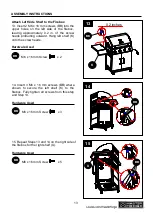
Page 13: ...t Side Shelf to the Firebox 13 Insert 2 M6 x 16 mm screws BB into the upper holes on the left side of the firebox leaving approximately 0 2 in of the screw heads protruding outward Hang left shelf K onto the screw heads Hardware Used M6 x 16 mm Screw X 6 AA M4X8mm Screw x 2 BB 0 2 inches BB K 13 15 Repeat Steps 13 and 14 on the right side of the firebox for the right shelf U Hardware Used M6 x 16 ...

Page 14: ...14 ASSEMBLY INSTRUCTIONS 16 Open the lid assembly A place the flame tamers I cooking grates H and warming rack G as shown I G H 16 17 Assembly is now complete 17 ...

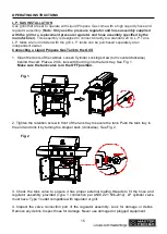
Page 15: ... the cabinet Loosen Cylinder Locking screw turn counterclockwise behind the cart Place a 20 Ib tank with foot ring into the tank tray See Fig 1 Make sure the tank valve is in the OFF position 2 Tighten the retention screw in front of the tank tray to secure the tank Push the tank tray to the end and lock it by turning the stopper back clockwise See Fig 2 3 Check the tank valve to ensure it has pro...

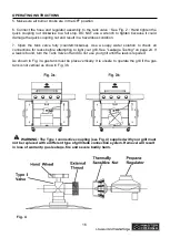
Page 16: ...ter solution to check all connections for leaks before attempting to light your grill See Leakage Testing on page 24 If a leak is found turn the Tank Valve off and do not use your grill until the leak is repaired As shown in Fig 3a gas tank must be place vertically It is unsafe to operate the grill if the gas tank is not vertical as show in Fig 3b WARNING The Type I connective coupling see Fig 4 s...

Page 17: ...on of Dangerous Goods and Commission L P TANK USE When turning the L P tank on make sure to open the valve SLOWLY two 2 complete turns to ensure proper gas flow Most gas tanks now come equipped with a leak detector mechanism internal to the tank When gas is allowed to escape rapidly it shuts off the gas supply Opening the valve rapidly may simulate a gas leak causing the safety device to activate ...

Page 18: ...er control knobs see Fig 6 6 Turn the top knob of the fuel supply cylinder counterclockwise two 2 rotations to open 7 Apply the soap solution to connections of the fuel supply assembly Spoon leak check solution at all X locations see Fig 7 If no soap bubbles appear there is no gas leak If bubbles form at the connections a leak is detected If a leak is detected immediately turn off the gas supply t...

Page 19: ...ed with a leak detector mechanism internal to the tank When gas is allowed to escape rapidly it shuts off the gas supply A leak may significantly reduce the gas flow making the grill difficult to light or causing low flames WARNING Do not use the grill in garages breezeways sheds or any enclosed area Never operate the grill in enclosed areas as this could lead to a carbon monoxide buildup which co...

Page 20: ...ill is located on a level surface 2 Keep the gas grill area clean and free from combustible materials gasoline and other flammable vapors and liquids 3 Ensure nothing is obstructing the flow of combustion and ventilation air 4 Ensure the ventilation of the cylinder enclosure is free and clear of debris 5 Visually check burner flames WARNING Heat and smoke exhaust out of the back of the grill hood ...

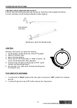
Page 21: ...ontrol knobs are in the OFF position 2 Open LP cylinder valve 3 Open lid during lighting 4 Press and turn the knob slowly to HIGH position The burner should light within three attempts 5 If burner does not light turn the knob to OFF wait 5 minutes and then repeat step 4 6 Once burner is lit rotate knob to desired heating level from High to Low FOR COMPLETE SHUTDOWN 1 Turn the knob to HIGH position...

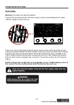
Page 22: ...ble and pass the match extender to the ports of the main burner tubes Position the match near the burner ports and push and turn the control knob counter clockwise to the HIGH position After the burner has lit turn the knob to the LP LOW position and carefully place the flame tamers and grates back in position Then turn the control knob to the desired setting NOTE If the grill will not light after...

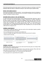
Page 23: ...n escape route Accordingly never operate your grill with very little or no open space at the cooking surface the cooking grids provide sufficient space Also never cover the ventilation louvers with foil or other materials that prevent air flow Specifically do not cover the entire surface with foil a large pan etc GENERAL MAINTENANCE Keep outdoor cooking gas appliance area clear and free from combu...

Page 24: ...STAINLESS STEEL After initial usage areas of the grill may discolor from the intense heat given off by the burners This is normal Purchase a mild stainless steel cleaner and rub in the direction of the grain of the metal Specks of grease can gather on the surface of the stainless steel and bake on to the surface and give a worn appearance For removal use a non abrasive grill cleaner in conjunction...

Page 25: ...eaks Excessive flare up 1 Grilling fatty meats 2 Knobs on HIGH 3 Spray water on gas flames 4 Hood closed when grilling 1 Move the meats to the warming rack if flare up continues until flame settles down 2 Grill fatty meats when the grids are cold while the knobs are on the LP LOW when using LP Gas 3 Never spray water on gas flames 4 Hood up when grilling Burner blows out 1 LP tank is empty 2 Burne...

Page 26: ...nly We are not responsible for incidental or consequential damages or labor costs This warranty does not cover corrosion or discoloration after the grill is used or lack of maintenance hostile environment accidents alterations abuse or neglect This warranty does not cover damage caused by heat abrasive and chemical cleaners or any damage to other components used in the installation or operation of...

Page 27: ...27 EXPLODED VIEW BB AA 12 3 45 6 7 8 10 9 11 12 13 14 15 16 17 18 19 20 21 22 23 24 25 26 27 28 29 30 32 31 33 34 35 36 37 38 39 40 41 45 43 44 42 46 47 48 ...

Page 28: ...406913 4 12 Spark Pin 2409830 4 13 Gas Valves And Gas Tube Assembly 5208081 1 14 Regulator And Hose Assembly 5207889 1 15 Control Panel Assembly 5208095 1 16 Knob Bezel 2409209 4 17 Knob 2307517 4 18 Firebox Assembly 5207868 1 19 Heat Shield 5207746 1 20 Drip Tray 5208205 1 21 Grease Cup 5201953 1 22 Left Side Shelf Assembly 5207841 1 23 Left Side Shelf Panel 5207748 1 24 Left Back Leg Assembly 52...

Page 29: ... 1 37 Right Back Leg Assembly 5207810 1 38 Lockable Caster 2100504 2 39 Right Side Panel 5207812 1 40 Right Front Leg Assembly 5208100 1 41 Unlockable Caster 2404362 2 42 Left Door Assembly CH2724420 1 43 Door Handle Assembly 5201620 2 44 Door Handle Bezel 5201175 4 45 Door Handle Sleeve 2100481 4 46 Right Door Assembly CH2724460 1 47 Match Light Extension 2307247 1 48 Hardware Pack 5208105 1 Mast...

Page 30: ...imitéde cet appareil ou de tout autre appareil 2 Aucune bouteille de propane non branchée ne doit être entreposé e à proximité de cet appareil ou de tout autre appareil DANGER Si vous détectez une odeur de gaz 1 Coupez l alimentation en gaz de l appareil 2 Éteignez toute flamme nue 3 Ouvrez le couvercle 4 Si l odeur persiste tenez vous àdistance de l appareil et appelez immé diatement le fournisse...

Page 31: ... entreposez pas et n utilisez pas d essence ni tout autre liquide ou vapeur inflammable àproximitéde cet appareil ou de tout autre appareil 2 Ne rangez pas de bouteille de propane non raccordée àproximitéde cet appareil ni de tout autre appareil DANGER Si vous détectez une odeur de gaz 1 Coupez l alimentation en gaz de l appareil 2 Éteignez toute flamme nue 3 Ouvrez la porte du four 4 Si l odeur p...

Page 32: ...IÈRES Consignes de sécurité 33 Contenu de l emballage 35 Quincaillerie incluse 37 Instructions pour l assemblage 38 Mode d emploi 44 Entretien 52 Dépannage 54 Garantie 56 Vue éclaté e 57 Liste des pièces de rechange 58 ...

Page 33: ...ritaire du barbecue Si un tuyau présente des traces d usure ou d abrasion excessive ou est coupé vous devrez le remplacer avant d utiliser le barbecue L ensemble de tuyau de remplacement utilisédoit être celui qui est précisépar le fabricant 7 Assurez vous que l espace autour de votre barbecue est propre et exempt de matériaux combustibles d essence et d autres vapeurs ou liquides inflammables 8 N...

Page 34: ... et d autres problèmes liés aux fonctions reproductrices Lavez vous les mains après avoir manipulécet article 23 La combustion du propane génère des produits chimiques reconnus par l État de la Californie comme étant la cause de cancers d anomalies congénitales et d autres problèmes liés aux fonctions reproductrices IMPORTANT Nous vous encourageons fortement àlire attentivement ce manuel et à vous...

Page 35: ...35 CONTENU DE L EMBALLAGE 俄 C D J E G I H F A K L M N P O R Q O S T U V W X Y Z A1 A2 A3 A4 A5 B ...

Page 36: ...se 1 V Pied arrière droit 1 G Grille de maintien au chaud 1 W Roulette verrouillable 2 H Grille de cuisson 2 X Panneau latéral droit du chariot 1 I Protecteur de flamme 4 Y Pied avant droit 1 J Bouton 4 Z Roulette déverrouillable 2 K Tablette latérale gauche 1 A1 Porte droite 1 L Pied arrière gauche 1 A2 Manchon de la poignée de porte 4 M Panneau latéral gauche de chariot 1 A3 Collerette de la poi...

Page 37: ... l emballage avec la liste des pièces et celle de la quincaillerie incluse S il y a des pièces manquantes ou endommagées ne tentez pas d assembler l article Temps d assemblage approximatif 1 heure deux personnes Outils requis pour l assemblage tournevis àtête cruciforme non inclus clé incluse AA BB Vis M4 de 8 mm Qté 20 Vis M6 de 16 mm Qté 30 ...

Page 38: ...es vis M4 de 8 mm AA Quincaillerie utilisée Vis M4 de 8 mm X 6 AA M4X8mm Screw x 6 AA AA O M AA N 1 L 1 Fixez le pied avant gauche N le pied arrière gauche L et la glissière gauche du bac récepteur O au panneau gauche du chariot M comme il est illustré à l aide des vis M4 de 8 mm AA Quincaillerie utilisée Vis M4 de 8 mm X 6 AA M4X8mm Screw x 6 AA 3 Retirez de l aimant Q les vis et les écrous préas...

Page 39: ...xez le panneau d appui S entre le panneau latéral gauche de chariot M et le panneau latéral droit de l assemblage à l aide des vis M6 de 16 mm BB comme il est illustré Quincaillerie utilisée Vis M6 de 16 mm X 6 A M4X8mm Screw x 10 BB AA P 6 AA 6 Fixer la traverse de porte de chariot P au panneau latéral gauche et au panneau latéral droit àl aide des vis M4 de 8 mm AA comme il est illustré Quincail...

Page 40: ...éité plats les rondelles à ressort et les vis M6 de 20 mm à l intérieur 9 2 Retirez de la jauge de température B le joint d étanchéité plat et l écrou à oreilles Puis fixez la jauge de température B à l ensemble de couvercle A comme il est illustré en prenant soin de placer le joint d étanchéité plat et l écrou à oreilles à l intérieur 9 3 Placez les boutons J comme il est illustré puis appuyez su...

Page 41: ...A2 et les collerettes de poignée de porte A3 Fixez ensuite une poignée de porte A4 àla porte gauche A5 et une autre àla porte droite A1 comme il est illustré à l aide des vis M5 de 16 mm en prenant soin de placer les manchons de poignée de porte A2 à l intérieur A1 A5 A2 A3 A4 11 BB BB BB 10 Vis M6 de 16 mm X 6 AA M4X8mm Screw x 4 10 Fixez l ensemble de l étape 9 àla base à l aide des vis M6 de 16...

Page 42: ...dans les trous supérieurs du côté gauche de la chambre de combustion Laissez les têtes de vis dépasser d environ 5 08 mm Accrochez la tablette latérale gauche K sur les vis BB Quincaillerie utilisée 0 2 inches BB K 13 Vis M6 de 16 mm X 6 AA M4X8mm Screw x 2 BB 5mm BB 14 14 Insérez 3 vis BB dans les trous inférieurs comme il est indiqué sur la tablette latérale gauche K de la chambre de combustion ...

Page 43: ...NS POUR L ASSEMBLAGE 16 Ouvrez l ensemble de couvercle A placez le protecteur de flame I les grilles de cuisson H et la grille de maintien au chaud G comme illustré I G H 16 17 L assemblage est maintenant terminé 17 ...

Page 44: ...ière du chariot Placez une bouteille de 9 07 kg dans le bac àréservoir Voir fig 1 Assurez vous que le robinet du réservoir est en position d arrêt OFF 2 Serrez la vis de rétention située devant le plateau pour bouteille afin de fixer la bouteille Poussez le plateau pour bouteille jusqu au fond puis verrouillez le en replaç ant le butoir faites le pivoter dans le sens des aiguilles d une montre Con...

Page 45: ...nsultez la section Vérification des fuites avant utilisation à la page 61 Si vous trouvez une fuite fermez le robinet de la bouteille n utilisez pas le barbecue jusqu à ce que les ré parations né cessaires aient étéeffectuées La bouteille de propane doit être placée à la verticale comme illustrée àla fig 3a Il n est pas sécuritaire d utiliser le barbecue si la bouteille de propane n est pas en pos...

Page 46: ...ane doit être munie d un dispositif de prévention des trop pleins et son robinet doit être muni d un collet protecteur La bouteille de propane doit être fabriquée et identifiée conformément aux normes du Department of Transportation DOT des États Unis pour de tels réservoirs ou à la norme nationale du Canada CAN CAS B339 Bouteilles et tubes utilisés pour le transport des marchandises dangereuses U...

Page 47: ... d une flamme nue 4 Mélangez dans des proportions égales un détergent doux ou du savon à vaisselle et de l eau 5 Fermez les boutons de commande du brûleur consultez la fig 6 6 Tournez le bouton supérieur de la bouteille de propane de deux 2 tours dans le sens contraire des aiguilles d une montre pour l ouvrir 7 Appliquez la solution savonneuse sur les raccords de l ensemble d alimentation en gaz S...

Page 48: ...bit ce qui rend le barbecue difficile àallumer ou entraî ne une diminution de la hauteur des flammes AVERTISSEMENT N utilisez pas le barbecue dans un garage un passage recouvert une remise ou tout autre espace clos N utilisez jamais le barbecue dans des espaces clos car cela pourrait entraî ner une accumulation de monoxyde de carbone et causer des blessures ou la mort Placez le barbecue sur une su...

Page 49: ... l espace autour du barbecue est propre et exempt de matériaux combustibles d essence et d autres vapeurs ou liquides inflammables 3 Assurez vous que rien n entrave le flux d air de combustion et de ventilation 4 Assurez vous que les orifices de ventilation de la bouteille de propane sont exempts de débris 5 Examinez les flammes des brûleurs AVERTISSEMENT Vérifiez si la conduite d alimentation en ...

Page 50: ...rcle lors de l allumage 4 Appuyez sur le bouton et tournez le lentement àla position HIGH élevée Le brûleur devrait s allumer après un maximum de trois tentatives 5 Si le brûleur ne parvient pas às allumer placez le bouton à la position OFF position d arrêt attendez 5 minutes puis répétez l étape 4 6 Lorsque le brûleur est allumé tournez le bouton de commande vers le niveau de chaleur souhaitéentr...

Page 51: ...n de commande et tournez le dans le sens contraire des aiguilles d une montre jusqu à la position HIGH élevée Une fois le brûleur allumé tournez le bouton àla position LP LOW faible et replacez soigneusement le protecteur de flamme et les grilles Tournez ensuite le bouton de commande àla température désirée REMARQUE Si le barbecue ne s allume pas après plusieurs essais consultez la section Dépanna...

Page 52: ...es de cuisson offrent suffisamment d espace De plus ne couvrez jamais les évents de papier d aluminium ou d autres matériaux qui nuisent à la circulation de l air En particulier évitez de couvrir la surface entière à l aide de papier d aluminium d une grande casserole etc ENTRETIEN GÉNÉRAL Gardez l espace autour de l appareil de cuisson au gaz pour l extérieur dégagé et exempt de matériaux combust...

Page 53: ...CIER INOXYDABLE Après l usage initial il est normal que certaines surfaces du barbecue viennent àperdre de leur couleur en raison de la chaleur intense émise par les brûleurs Cela est normal Achetez un nettoyant doux pour acier inoxydable et frottez dans le sens du fil du métal Des gouttes de graisse peuvent s accumuler sur la surface de l acier inoxydable et cuire donnant au métal un aspect vieil...

Page 54: ...lez l ouverture pour obtenir des flammes bleues L ouverture doit être de 0 64 cm pour le propane L ouverture doit être de 0 32 cm ou moins pour le gaz naturel 2 Enlevez ce qui obstrue les orifices 3 Déterminez la source des fuites de gaz Des flambées excessives se produisent 1 Les viandes cuites sont grasses 2 Les boutons sont àla position HIGH élevée 3 De l eau a été versée sur les flammes 4 Le c...

Page 55: ...e comporte un dispositif de régulation de dé bit conç u pour assurer une alimentation suffisante en gaz au barbecue Des changements rapides dans la pression peuvent activer le dispositif de régulation du débit produisant une flamme plus petite et une température peu élevée Veuillez suivre les instructions ci dessous 1 Assurez vous que tous les brûleurs sont àla position OFF arrêt 2 Ouvrez le robin...

Page 56: ...ni des coûts de main d œuvre La présente garantie ne couvre pas la corrosion ni la décoloration une fois que le barbecue a été utilisé ni les dommages causés par le manque d entretien un milieu hostile un accident la transformation de l article l utilisation abusive ou la négligence La présente garantie ne couvre pas les dommages causés par la chaleur les produits nettoyants abrasifs ou chimiques ...

Page 57: ...57 VUE ÉCLATÉE BB AA 12 3 45 6 7 8 10 9 11 12 13 14 15 16 17 18 19 20 21 22 23 24 25 26 27 28 29 30 32 31 33 34 35 36 37 38 39 40 41 45 43 44 42 46 47 48 ...

Page 58: ...06913 4 12 Tige d allumage 2409830 4 13 Ensemble de robinets de gaz et de tuyau d alimentation en gaz 5208081 1 14 Régulateur Et tuyau 5207889 1 15 Panneau de controle 5208095 1 16 Collerette de bouton 2409209 4 17 Bouton 2307517 4 18 Chambre de combustion 5207868 1 19 Bouclier thermique 5207746 1 20 Bac récepteur 5208205 1 21 Bac ramasse graisse 5201953 1 22 Tablette latérale gauche 5207841 1 23 ...

Page 59: ...arrière droit 5207810 1 38 Roulette verrouillable 2100504 2 39 Panneau latéral droit du chariot 5207812 1 40 Pied avant droit 5208100 1 41 Roulette déverrouillable 2404362 2 42 Porte gauche CH2724420 1 43 Poignée de porte 5201620 2 44 Collerette de poignée de porte 5201175 4 45 Manchon de la poigné e de porte 2100481 4 46 Porte droite CH2724460 1 47 Tige d allumage pour allumette 2307247 1 48 Trou...

Reviews: