background image

4

1. Information

SUPPLIED BY:

Shinerich Industrial Ltd.

Product Name

OUTDOOR GAS BBQ

Model No.

SRGG51111/SRGG51112

PIN Number

359CL1089

Qn

19.6 kW(1401g/h)

Main burners

Qn :

16.1 kW(1151g/h)

Side burner


3.5 kW (250 g/h)

Country

Category

Injector Size
(Main Burner)

Injector Size
(Side Burner)

Gas & Pressure

AT

CH

DE

SK

I

3B/P(50)

0.76 mm

 0.79 mm

G30

Butane

and

G31

Propane at 50mbar

BE

CY

DK

EE

FR

FI

HU

IT

LT

NL

NO

SE

SI

SK

RO

HR

TR

BG

IS

LU

MT

I

3B/P(30)

0.87 mm

0.90 mm

G30 Butane

and

G31

Propane at 30mbar

BE

CH

CY

□CZ

ES

FR

GB

GR

IE

IT

LT

LU

LV

PT

SK

SI

I

3+(28-30/37)

G30 Butane at 28-30 mbar
and G31 Propane at 37mbar

CAUTION :

USE OUTDOORS ONLY. If stored indoors, detach and leave cylinder outdoors.
Read the instructions before using the appliance.
Minimum clearance from side and back of unit to combustible construction: 100cm.
WARNING: Accessible parts may be very hot. Keep young children away.

MADE IN CHINA

0359

8/F, Noble Center No.1006, 3rd Fuzhong Road

Futian District, Shenzhen, China

0.87 mm

0.90 mm

Summary of Contents for Connoisseur 600 SRGG51111

Page 1: ...ANCE WITH BS EN498 2012 and BS EN 484 1998 STANDARD Manufactured by SHINERICH INDUSTRIAL LTD 8 F NOBLE CENTER NO 1006 3RD FUZHONG RD FUTIAN DISTRICT SHENZHEN CHINA Propane Gas Barbecue User Manual Ireland Importer Distributor Home Store More Unit 4 Parkway House Ballymount Drive Dublin 12 ...

Page 2: ...tely contact your gas supplier or fire department IMPORTANT Hazardous fire or explosion may result if these instructions are ignored It is the user s responsibility to see that this barbecue is properly assembled installed and taken care of Failure to follow instructions in this manual could result in serious bodily injury and or property damage Any modification of the appliance misuse or failure ...

Page 3: ...ormation 4 2 Safety instructions 5 3 Explode view Hardware 6 4 Assembly instructions 9 5 Installing with gas supply system 17 6 Operating instructions 18 7 Cleaning and maintenance 20 8 Troubleshooting 21 9 Limited Warranty 22 ...

Page 4: ...LT NL NO SE SI SK RO HR TR BG IS LU MT I3B P 30 0 87 mm 0 90 mm G30 Butane and G31 Propane at 30mbar BE CH CY CZ ES FR GB GR IE IT LT LU LV PT SK SI I3 28 30 37 G30 Butane at 28 30 mbar and G31 Propane at 37mbar CAUTION USE OUTDOORS ONLY If stored indoors detach and leave cylinder outdoors Read the instructions before using the appliance Minimum clearance from side and back of unit to combustible ...

Page 5: ...nd inspect the hose before each use of the appliance If there is evidence of abrasion wear cuts or leaks the hose must be replaced prior to the appliance being operated Use only factory authorized parts The use of any part that is not factory authorized is dangerous This may also void your warranty When cooking fire extinguishing materials shall be readily accessible In the event of an oil grease ...

Page 6: ...6 EXPLODED VIEW 1 2 3 4 5 6 7 8 9 10 11 12 13 14 15 16 17 18 19 20 21 22 23 24 25 26 27 31 29 32 30 28 35 33 34 ...

Page 7: ...le Front right pole Rear right pole Right transom Right side shelf Right side burner bowl Ignition pin Right side burner Right side burner rack Right burner lid Grill body Side burner valve Bottom panel Side shelf handle bezel Side shelf handle 1 1 2 5 5 1 1 4 6 6 1 1 1 1 1 2 2 1 1 1 1 1 1 1 1 1 1 1 1 1 1 2 1 1 2 3 4 5 6 7 8 9 10 11 12 13 14 15 16 17 18 19 20 21 22 23 24 25 26 27 28 29 30 31 32 33...

Page 8: ... AA BB DD EE 15 2 4 2 M5 x 12 wing bolts M6 x 12 wing bolts D5 washers D10 washers FF 4 R pins GG 1 PP washer HH 2 M10 nuts TOOLS REQUIRED HARDWARE CC 8 M5 x 12 bolts Phillips Head Screwdriver Not included Adjustable Wrench Not included ...

Page 9: ... 2pcs GG PP washer 1pc HH M10 nuts 2pcs 21 20 FF 22 Attach 1 PP washer GG 2 D10 washers EE 2 wheels 19 2 M10 nuts HH 2 R pins FF and 2 wheel caps 18 to the axle 20 and secure them in turn as illustrated 18 FF GG 20 EE 19 HH Insert the axle 20 through the front right pole 21 and rear right pole 22 secure them with 2 STEP 1 STEP 2 ...

Page 10: ... transom 23 to front right pole 21 and rear right pole 22 fix them with 4 M5 x 12 wing bolts AA 21 23 22 AA M5 x 12 wing bolt Hardware Used 4pcs 13 14 15 AA STEP 3 STEP 4 AA Attach left transom 13 to front left pole 15 and rear left pole 14 fix them with 4 M5 x 12 wing bolts AA ...

Page 11: ...sed 3pcs 21 17 15 AA 32 21 14 15 22 1 Insert the 2 pre installed bolts on bottom panel 32 into the two key holes on front left pole 15 and front right pole 21 2 Insert the 2 pre installed bolts on bottom panel 32 into the two key holes on rear left pole 14 and rear right pole 22 3 Press down the bottom panel 32 to position and secure it to the rear left pole 14 and rear right pole 22 with 3 M5 x 1...

Page 12: ...lled bolts on condiment shelf 16 to position as shown Then fix condiment shelf 16 onto front left right poles 15 21 with 2 M5 x 12 bolts CC as illustrated 16 15 CC 21 16 STEP 7 STEP 8 Hardware Used CC M5 x 12 bolts 2pcs Place the grill body 30 onto the assembled cart secure it with 4 D5 washers DD and 4 M5 x 12 wing bolts AA AA D5 washers Hardware Used 4pcs DD M5 x 12 wing bolts 4pcs DD 30 AA ...

Page 13: ...side shelf 7 with 2 M6 x 12 bolts BB 2 Install left side shelf 7 onto grill body 30 with 4 M5 x 16 bolts which are pre installed on the grill body 30 as illustrated and keep them half loosen Locking front panel of left side shelf 7 to main control panel with 2 M5 x 12 bolts CC Then tighten all the 6 bolts 3 Repeat the same procedure to install right side shelf 24 7 24 CC M5 x 16 bolts 4pcs pre ins...

Page 14: ...the nozzle of side burner valve 31 into the injection pipe of right side burner 27 2 Place the other end of side burner valve 31 through the hole on the front panel of right side shelf 24 fix it to control knob bezel 11 with another two pre installed M4 x 10 bolts from side burner valve 31 then install control knob 12 onto the shaft of side burner valve 31 3 Screw two M4 x 10 bolts mentioned in 1 ...

Page 15: ...on wire to the ignition pin 26 on the right side burner bowl 25 Note Manually adjust the gap between the ignition pin and the flame orifice around 3 5mm 0 1 0 2inch to ensure proper ignition 26 Flame orifice Ignition pin Ignition wire 26 25 27 STEP 11 ...

Page 16: ...es 3 and warming rack 2 into the grill body 30 in turn CC M5 x 12 bolt Hardware Used 2pcs CC 2 3 4 30 STEP 12 Fix grease tray 6 onto the grill body 30 with 2 M5 x 12 bolts CC install grease cup 34 into grease cup hanger 33 and then hang them onto the bottom of grease tray STEP 13 ...

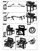
Page 17: ...is not subject to twisting Disconnect LP Gas cylinder Before disconnecting make sure the LP gas tank valve in CLOSED Disconnect gas line from LP gas cylinder by turning knob counterclockwise until it is loose After connecting to gas cylinder a leak testing is necessary Danger When changing the gas container care must be taken to keep away from any source of ignition Leak Testing To be performed in...

Page 18: ...bs are in Ɣ position 4 Connect regulator with cylinder then turn on 5 Push and turn control knob anti clockwise to approx 1 4 position until a click is heard and burner is lit 6 Adjust the flame between 1 4 to 1 2 areas If the burner still fails to light after several attempts try the manual ignition procedure below 1 Open BBQ hood 2 Ensure all the burners control knobs are in the Ɣ position 3 Slo...

Page 19: ... levels warming rack 5 To avoid losing natural juice use long handled tongs or spatulas instead of forks and turn foods over just once during cooking 6 When direct cooking adjust your burners to different levels so foods can be prepared to different internal temperatures in the same time frame 7 Try water pans to reduce flare ups and cook juicer meats Before starting barbecue remove cooking grids ...

Page 20: ...bes Use a pipe cleaner to clear obstructions A wire brush can be used to remove corrosion from the burner surfaces When refitting the burner be careful to check that the venture tubes of the burner fit over the valve outlets 3 Barbecue Body Regularly remove excess grease or fat from the barbecue body with a soft plastic or wooden scraper It is not necessary to remove all the grease from the body I...

Page 21: ...device by turning control knobs OFF and LP gas cylinder valve to CLOSED Disconnect regulator Turn control knobs to HIGH wait 1 minute Then turn control knobs to OFF and reconnect regulator and leak check connections Slowly turn LP gas cylinder valve to OPEN wait 30 seconds and then light barbecue per lighting instructions Irregular flame pattern flame does not run the full length or burner Burner ...

Page 22: ... warranty includes manufacturing deficiencies and defective parts it extends to the replacement of these parts Expenses for shipping installation replacement of worn parts and other cost are not covered by the warranty The warranty lapses in case of mishandling and if any kind of unauthorized modifications are made on the unit ...

Reviews: