background image

05

06

1.1.4 Safe maintenance habits 

* To open the meter shell or remove the battery cover, you 
   should first pull out the test probe. 
* When performing meter maintenance, you should use 
   specified replacement parts.* Before opening the meter, 
   you should disconnect all power supplies and ensure that 
   you have no static electricity to avoid damaging the meter 
   components. 
* Meter calibration, maintenance, repair and other operations 
   only can be performed by technicians who fully understand 
   the meter and electrical shock hazards. 
* Before opening the meter, you should be aware that there 
   may be dangerous voltages remaining in some capacitances 
   in the meter even after powering off. 
* If you find any abnormal phenomena on the meter, the meter 
   should be immediately turned off and repaired. Ensure that it 
   can not be used before passing inspection. 
* When the meter is not used for a long time, please remove 
   the battery and avoid storing it in a high temperature and 
   humidity environment.

1.2 Input protection measures  

* When making voltage measurements (not including 200mV 
   grade), the maximum input voltage is 600V DC or 600V AC. 
(The maximum input voltage of 200mV grade is 250V AC or 
equivalent RMS value voltage). 
* When making frequency, resistance, on-off and diode 
   measurements, the maximum voltage is 250V AC or 
   equivalent RMS value voltage. 
* When making capacitance, temperature, mA current, and 
   triode hFE measurements, the meter is protected through 
   a fuse (FF 400mA H 600V). 

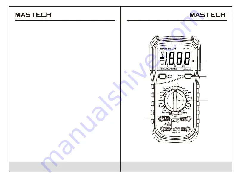
2. Meter appearance description

2.1. Meter appearance

1. LCD

(

liquid


crystal


display

)  

     2. Mains Switch    

3. HOLD Key      4. Rotary Switch    5. Input Socket

1

3

4

5

2

Summary of Contents for MY70

Page 1: ...MY70 74 74B OPERATION MANUAL DIGITAL MULTIMETER CAT III 600V ...

Page 2: ...iode 11 3 2 4 Audible continuity testing 12 3 2 5 Measuring capacitance MY74 MY74B 12 3 2 6 Transistor measuring 3 2 7 Measuring frequency MY74 MY74B 3 2 8 Measuring temperature MY74 MY74B 3 2 9 Measuring current 4 Technical indicators 4 1 Comprehensive indicators 4 2 Accuracy indicators 4 2 1 DC voltage 4 2 3 Frequency only for MY74 MY74B 4 2 4 Resistance 4 2 5 Diode 4 2 6 Audible continuity 19 4...

Page 3: ...meter When the meter is connected to the circuit being measured do not touch the unused input end When the voltage to be tested exceeds 60Vdc or 30Vac effective value please operate carefully to prevent electric shock When you measure with test probe first connect the common testing end of black test probe to the common testing end of circuit to be tested then connect red test leads to the test ci...

Page 4: ...ircuits being tested The TV filter should be used to weaken these pulses to avoid the meter damage This meter uses a 9V 6F22 battery The battery should be properly installed in the meter s battery compartment When the battery indicator appears the battery should be replaced immediately Low battery will cause meter reading errors and possibly result in electric shock or personal injury When you mak...

Page 5: ...nomena on the meter the meter should be immediately turned off and repaired Ensure that it can not be used before passing inspection When the meter is not used for a long time please remove the battery and avoid storing it in a high temperature and humidity environment 1 2 Input protection measures When making voltage measurements not including 200mV grade the maximum input voltage is 600V DC or 6...

Page 6: ... the battery should be replaced immediately Symbols Indication Negative input polarity indication Keep the current measurement value HOLD Table 2 Input Socket COM mA 2 2 LCD display See Table 1 for information about the display Fig 1 Display HV High voltage symbol in AC600V or DC600V Positive input end of voltage resistance frequency diode buzzer measurement and temperature test connected with the...

Page 7: ...e 1 Rotate the switch to the appropriate position 2 Respectively connect black and red test probe to COM input socket and V input socket 3 Measure the voltage of circuit to be tested with other two ends of test probes Connected with the circuit to be tested in parallel 4 Read the measuring voltage value from LCD display When measuring DC voltage the display will simultaneously show the voltage pol...

Page 8: ...diode should still produce a forward voltage drop of 0 5V to 0 8V but the reverse bias voltage will vary depending on resistance values of other channels between two test probes 3 2 4 Audible continuity testing To avoid damaging meter or device to be measured before testing buzzer continuity cut off all circuits being tested and discharge all high voltage capacitors To make continuity testing 1 Ro...

Page 9: ...h electric quantity higher than 60V DC or 24V AC RMS to prevent electrical shock Don t measure the temperature in a microwave oven to prevent fire or meter damage 3 2 9 Measuring current When the ground voltage of open circuit voltage exceeds 250V do not try to make current measurements on the circuit If the fuse is blown when making a measurement you may damage the meter or injure yourself To avo...

Page 10: ...g range 6 Cut off the power supply of circuit to be tested Discharge all high voltage capacitors Remove the test probe of meter and restore the circuit to its original condition 4 Technical indicators 4 1 Comprehensive indicators Operating environment and condition 600V CAT III pollution grade 2 Elevation 2000 m Environment temperature and humidity O 0 40 C 80 RH 10 C it is not to be considered St...

Page 11: ... or 600V ac RMS 250Vdc or ac RMS with the measuring range of 200mV Frequency response 40Hz 400Hz sine wave RMS average response The frequency response is 200Hz for 600V 4 2 3 Frequency only for MY74 MY74B Measuring range Resolution Accuracy 20kHz 10Hz 2 0 of reading 5digits Input voltage range 200mV 10V ac RMS Overload protection 250V dc or 250V ac RMS 4 2 4 Resistance Measuring range Resolution A...

Page 12: ...eading 1digits 20μA for MY70 MY74B 200μA only for MY70 20mA 200mA 2mA for MY70 MY74 10A 0 01μA 0 1μA 1μA 10μA 0 1mA 10mA 1 5 of reading 1digits 2 0 of reading 5digits Overload protection fuse with measuring range of mA FF400mA H 600V fuse with measuring range of 10A FF10A H 600V Maximum input current mA grade 200mA DC or AC RMS 10A grade 10A DC or AC RMS When measured current is greater than 10A c...

Page 13: ... avoid electrical shock or personal injury before opening the battery cover to replace battery you should turn the meter off and make sure that the test probe is disconnected from the measurement circuit 5 3 Replacing Test Leads WARNING WARNING WARNING Use meet EN 61010 031 standard rated CAT III 600V 10A or better test leads Please follow below steps to replace battery or fuse 1 Turn off the powe...

Page 14: ...00 05 4176 ...

Reviews: