background image

Symbol

Description

V

,

mV

V:
mV:

Volts. The unit of voltage.
Millivolt. 1x10  or 0.001 volts.

A,mA,µA

A:
mA:
µA

:

Amperes (amps). The unit of current.
Milliamp. 1x10  or 0.001 amperes.
Microamp. 1x10  or 0.00001 amperes.

Ω

Ω

Ω

,K ,M

Ω

:

k

Ω

:

M

Ω

:

Ohm. The unit of resistance.
Kilohm. 1x10  or 1000 ohms.
Megohm. 1x10  or 1,000,000 ohms.

Hz,KHz,MHz

Hz:
KHz:
MHz:

Hertz. The unit of frequency.
Kilohertz. 1x10  or 1000 hertz.
Milohertz. 1x10  or 1,000,000 hertz.

Hz,KHz,MHz

F:
mF:
μF:
nF:

Farad. The unit of capacitance.
Millifarad. 1x10  or 0.001 farads.
Microfarad. 1x10  or 0.000001 farads.
Nanofarad. 1x10  or 0.000000001 farads.

-3

-3

-6

3

6

3

6

-3

-6

-9

3. Technical specifications

3.1 General specifications

Safety Rating: CAT III 600V, pollution degree of 2
Operating Altitude: <2000m
Operating Temperature/Humidity: 0~40

, <80% RH

Storage Temperature/Humidity: -10~60

, <70% RH, 

                                                        remove battery
Max. Input between terminals and earth ground: 600V DC 
          or AC True-RMS
Fuse Protection: A/mA ranges: FF 400mA H 1000V 
                             10A range: FF 10A H 600V
Display: 3³⁄4 digit LCD display
Overload Indication: Display shows “OL”

Low Battery Indication: When battery voltage drops below 
                                         normal operating voltage, “     ” is 
                                         shown on the display
Polarity Indication: Display automatically displays “-”
Power Supply: DC 9V (NEDA 1604, 6F22 or 006P)
Wireless Communication Distance: 
                                                     Indoor/Outdoor: <10m
Supported App OS: iOS: 7.0 and above
                                  Android: 4.3 and above
Size(LxWxH): Approx. 92x188x50mm
Weight: Approx. 432g

Accurancy: ±( % r digits ) at 18

~28

 with a 

relative humidity of <80%; guaranteed for a period of 
one year.

3.2 Technical indicators
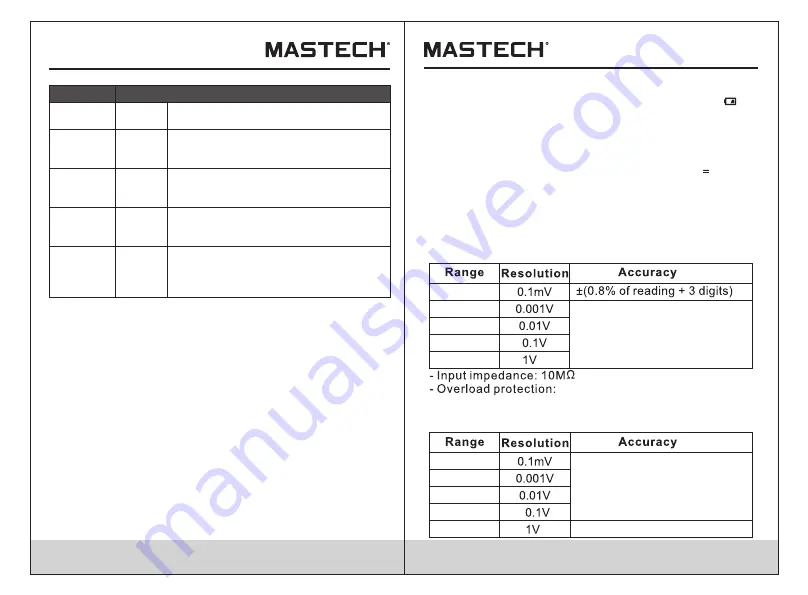
3.2.1 Dc voltage

400mV

4.0V

40V

400V

600V DC or AC True-RMS.

600V

±( 1% of r 5 digits )

- Max. input voltage: 600V DC or AC True-RMS.

400mV

4.0V

40V

400V

3.2.2 Ac voltage

±( 1.0% of r 8 digits )

09

10

600V

±( 1.2% of r 8 digits )

Summary of Contents for MS8361D

Page 1: ...MS8361D CAT III ...

Page 2: ...3 2 10 Frequency 3 2 10 1 In V mode 3 2 10 2 In ηA mA A mode 3 2 10 3 In Hz mode 3 2 10 4 Duty ratio 4 Operating instructions 4 1 AC DC Voltage measurement 4 2 AC DC Current measurement 4 3 Resistance measurement 4 4 Continuity measurement 1 1 2 3 4 5 5 7 8 8 9 9 10 10 10 11 11 11 12 12 13 13 13 13 14 14 15 16 16 16 17 18 4 5 Diode test 4 6 Capacitance measurement 4 7 Transistor measurement 4 8 Fr...

Page 3: ...erference and 2 this device must accept any interference received including interference that may cause undesired operation This equipment has been tested and found to comply with the limits for a Class B digital device pursuant to part 15 of the FCC Rules These limits are designed to provide reasonable protection against harmful interference in a residential installation This equipment generates ...

Page 4: ... as per the specification herein AC Alternating Current DC Direct Current Conforms to UL STD 61010 1 61010 2 030 61010 2 033 Certified to CSA STD C22 2 NO 61010 1 61010 2 030 61010 2 033 Complies with European EU safety standards CAT III MEASUREMENT CATEGORY III is applicable to test and measuring circuits connected to the distribution part of the building s low voltage MAINS installation ...

Page 5: ...rt area The multimeter is a portable hand held yet professional meter that features true RMS measurement display AC DC current AC DC voltage Frequency Capacitance Resistance Communication non contact voltage tests and hEF tests This meter is easy to use even with one hand suitable for professional user or amateurs and ideal for school or home use Both auto and manual range Display hold True RMS fo...

Page 6: ...ter and show any measurement being performed Press again to disconnect the meter from the mobile device Hz DUTY button Press Hz DUTY to start the frequency counter Press Hz DUTY again to enter duty cycle mode Press Hz DUTY again to exit the frequency counter mode REL button Press REL to enter and exit the relative measurement mode 2 3 Auto power off function After 15 minutes of non use the meter w...

Page 7: ...rage Temperature Humidity 10 60 70 RH remove battery Max Input between terminals and earth ground 600V DC or AC True RMS Fuse Protection A mA ranges FF 400mA H 1000V 10A range FF 10A H 600V Display 3 4 digit LCD display Overload Indication Display shows OL Low Battery Indication When battery voltage drops below normal operating voltage is shown on the display Polarity Indication Display automatica...

Page 8: ...DC current 400μA 4000μA 40mA 400mA 10A 0 01mA 0 1mA 1 0 of reading 10 digits Overload protection mA jack FF 400mA H 1000V 10A jack FF 10A H 600V Max input current mA jack 400mA 10A jack 10A 3 2 7 AC current 400μA 4000μA 40mA 400mA 10A 0 01mA 0 1mA 1 5 of reading 5 digits 3 0 of reading 5 digits Overload protection mA jack FF 400mA H 1000V 10A jack FF 10A H 600V Frequency response 40 400Hz true RMS...

Page 9: ...oltage range 3V AC True RMS higher input voltage at higher frequency Input impedance 10MΩ Max input voltage 600V AC True RMS 3 2 10 2 In μA mA A mode 99 99Hz 999 9Hz 1KHz Input current range μA range 100μA AC True RMS mA range 10mA AC True RMS A range 5A AC True RMS higher input current at higher frequency Max input current μA range 400mA AC True RMS mA range 400mA AC True RMS A range 10 A AC True...

Page 10: ...the display Observe polarity for DC measurement In manual mode if OL is display it means the measurement has exceeded the current range Increase the selected range and measure again WARNING Do not measure voltages higher than 600V DC or AC rms to prevent damage to the meter or personal injury WARNING Never measure open circuit voltages exceeding 600V between the input terminals and ground to preve...

Page 11: ...played on the screen WARNING To prevent injury or damage to the meter turn off power to circuitand discharge all capacitors fully before making resistance measurements 4 4 Continuity measurement Turn off the power to the circuit Allow all capacitors to discharge Set the rotary switch to the multi function position Press FUNC twice to enter continuity mode Connect the red test lead to the input jac...

Page 12: ...termine whether the transistor to be tested is NPN or PNP type and locate the Emitter Base and Collector leads Insert leads of the transistor into proper holes of the special multi function socket WARNING To avoid eletrical shock and or damage to the instrument do not apply more than 36Vdc or 36Vac rms between the hFE terminal and the COM terminal 4 8 Frequency measurement Set the rotary switch to...

Page 13: ...horized personnel should make repairs to the meter To avoid injury or damage to the meter do not allow moisture inside the case and remove test leads before opening battery cover 5 2 Replacing the Battery WARNING To avoid false readings and potential dangerous situations replace the battery immidately when the symbol appears Turn off the meter and disconnect the test leads before opening the batte...

Page 14: ...Package Multi Function Socket 1 set R 00 05 2149 23 ...

Reviews: