background image

REL MAX MIN

%

AUTO

kHz

nmF

Hz

kM

C  F

mVA

0

10

20

30

40

50

60

66

MS8251B

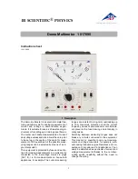
DIGITAL MULTIMETER

OPERATION MANUAL

MS8251B

Summary of Contents for MS8251B

Page 1: ...REL MAX MIN AUTO kHz nmF Hz kM C F mVA 0 10 20 30 40 50 60 66 MS8251B DIGITAL MULTIMETER OPERATION MANUAL MS8251B ...

Page 2: ...ry switch to the required function and range to be measured When using the CAT Ⅳ environment if the measuring voltage between terminals and earth ground exceeds 600V CAT III environments or voltage measurement between the terminal and the earth more than 1000V do not measure voltage Always be careful when working with voltages above 60V DC or 30V AC RMS Keep fingers behind the probe barriers while...

Page 3: ...age AC DC current resistance capacitance continuity diode test frequency and duty cycle Auto and manual range Auto power off Max measurement Min measurement Relative measurement Reading Hold function True RMS Simultaneously display frequency during AC voltage current measurements Non contact voltage test Meter complies with European Community EU standards Earth Ground 2 1 Components 1 2 3 4 Non co...

Page 4: ...EMP position thermocouple temperature measurement LO Z position identify ghost voltages turn off meter Temp V Hz jack voltage current resistance capacitance diode continuity frequency duty cycle temperature input terminal jack common input terminal µAmA jack current measurements 600mA 10A jack current measurements 600mA to 10A 2 3 LCD display REL MAX MIN AUTO kHz nmF Hz kM C F mVA 0 10 20 30 40 50...

Page 5: ...ower off 15 minutes 3 1 12 Power supply 9V 6F22 battery 3 1 13 Low battery indication LCD displays Temperature coefficient less than 0 1x specified accuracy C Operating temperature 0 C 40 C 3 1 16 Storage temperature 10 C 50 C 3 1 17 Dimensions 175 85 52mm 3 1 18 Weight approx 420g including battery 3 Specifications The Meter should be calibrated annually between 18 C 28 C and a relative humidity ...

Page 6: ... create a capacitive coupling between conductors If this possibility exists or when testing for the presence of voltage use the Lo Z mode to switch to the low impedance setting to remove the ghost voltages during measurement Input impedance 10MΩ Overload protection 660mV range 250V DC or AC RMS 6 6V 1000V range 1000V DC AC RMS Maximum input voltage 1000V DC 0 1mV 0 8 of reading 3 digits 660mV 0 00...

Page 7: ...edance 400kΩ Overload protection 660mV range 250V DC or AC RMS 6 6V 1000V range 1000V DC AC RMS Maximum input voltage 1000V AC RMS Response True RMS 0 1mV 1 5 reading 5 digits of 660mV 0 001V 0 01V 0 1V 6 6V 66V 660V 1 2 reading 5 digits of Resolution Accuracy range 1 0 reading 3 digits of 3 2 4 2 AC Voltage Low Impedance lo Z 1 2 reading 5 digits of 11 12 3 2 7 Diode Test Forward DC current 1mA a...

Page 8: ...tinue measurement for more than 10 sec Pause for 1 minute after the measuring 660 A µ 1 0 reading 5 digits 66mA 10A 0 1µA 1µA 10µA 10mA 2 0 reading 5 digits 6600 A µ 660mA 100µA Resolution Accuracy range Range 10Hz 10kHz Input Voltage 0 2V AC Input voltage should increase along with the frequency 3 2 9 Frequency 3 2 9 1 Frequency V position 66Hz 1 5 reading 5 digits 660Hz 6 6kHz 10kHz 0 01Hz 0 1Hz...

Page 9: ...the maximum value recorded 4 4 2 Press MAX MIN again to display the minimum value recorded 4 4 3 Hold MAX MIN to return to normal readings 4 4 Maximum Minimum Reading 4 5 Function Switching 4 6 Backlight 4 7 Automatic Power off 4 8 Non Contact Voltage Detection NCV 4 7 1 If there is no operation for 15 minutes after turning the machine on the meter will automatically power off to save the battery ...

Page 10: ...ack and the black test lead to the COM jack 4 11 3 Connect the test leads to the circuit 4 11 4 If the resistance of the circuit is less than 50Ω a buzzer will sound 4 12 Diode 4 12 1 In continuity mode press FUNC to switch to diode mode 4 12 2 Connect the red test lead to the input jack and the black test lead to the COM jack 4 12 3 Connect the red test lead to the anode and the black lead to the...

Page 11: ...nt exceeds the selected mode Move the rotary switch to the next higher position 5 Maintenance 5 1 Replace Battery To avoid electrical shock damage or personal injury remove test leads before openning battery cover 5 1 1 Note If the low battery symbol appears the battery needs to be changed 5 1 2 Unscrew the battery cover from the back of the meter and remove the old battery 5 1 3 Insert a new batt...

Page 12: ...00 05 3591 21 ...

Reviews: