background image

Fastening Methods and Jamb/Sill Screw Chart

Although structural installations may involve fastening with wood brick mould casing or nailing fin, there are two ways

to fasten your jambs to the opening for structural purposes:

1. #8 Wood screws (or 3/16

 concrete anchors), 6

 (152) from all corners and

   15

 (381) on center around the perimeter.

or

2. Structural brackets, 6

 (152) from all corners and 15

 (381) on center around the perimeter.

Refer to the 

“Jamb/Sill Screw Chart”

 for proper fastening requirements for your particular product. Illustrations

show a concrete block opening but apply to typical wood frame construction as well.

NOTE: All mulled units require fastening with two screws or brackets on each side of the mull joint no more than

6

,

 (152) from mull joint.

NOTE: Single UDH products do not require fastening at the sill. Multiple wide UDH assemblies require anchoring

at the sill mullion. UDHM IZ3 units must be installed with jamb screws, fastening at the sill is not required.

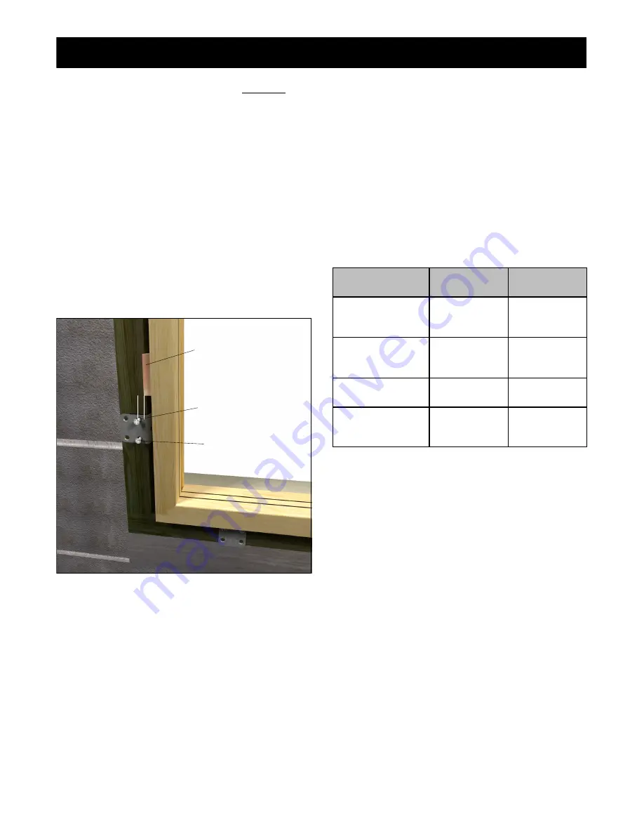
Jamb/Sill Screw Chart

Structural Brackets

1. Wrap brackets around the framing/buck/opening,

fasten with two #8 x 1 5/8

 screws. Angle the screws

approximately 15 degrees away from the window.

Always shim above or behind installation brackets.

Figure 7

1/4

5/32

 holes

Shim

Screws

Jamb/Sill Screws

1. Space fasteners along jambs and head jambs no

more than 6

 (152) from each corner and 15

 (381)

on center. Follow same spacing for sills when appli-

cable.

NOTE: Structural brackets are allowable replacements

for screws if fastening at the sill is necessary.

2. After removing covers or liners, fasten units to the

framing with #8 wood screws or 3/16

 concrete an-

chors

1

.  Adjust length of fastener so that it penetrates

no less than 1 1/4


(32)

 into framing/opening. When

fastening through the sill, always pre

drill and fill

hole with sealant before driving the screw. Always

place a shim behind or above the screw location on

jambs and head jambs.

NOTE:  When using masonry anchors, be sure to follow

manufacturer’s guidelines for proper installation. Some

types require pre

drilling.

1

Use concrete anchors when wood buck material is less than 2

 nominal thickness.

8

Window Installation

StormPlus and Structural Installations

19970019

2012

04

10

Product

Jamb Screw

Length

Sill Screw

Length

Clad Casemaster

Family and Direct

Glaze

3

 (76)

2 1/2

 (64)

Wood Casemaster

Family and Direct

Glaze

3

 (76)

3 1/2

 (89)

Ultimate Double

Hung Family

2 1/2

 (64)

N/A

Ultimate Double

Hung Magnum

Family*

Supplied

with unit

N/A

*  Use predrilled holes in frame members.

Summary of Contents for Window

Page 1: ... steps for installing your window included within are Rough opening RO preparation for recessed masonry applications RO prep and sealing details for standard wood frame construction detailed fastening methods and more The procedures within these instructions are consistent with those used in testing to achieve the advertised DP rating Contact your local Marvin dealer if your construction scenario ...

Page 2: ...w Chart 8 Wood Screws Concrete Anchors and Structural Brackets Special Fastening Systems 10 StormPlus Ultimate Double Hung IZ3 Storm Brackets Step Four Final Installation Procedures 11 Standard Frame Construction and Recessed Masonry Applications Continuous Air Barrier Systems 12 Installation Integration and window installation tips for house wrap Removing Interior Stops Liners and Fillers 14 Remo...

Page 3: ...ers and building papers sheathing and the window unit Flashing material must not contain asphalt and must be compatible with flexible PVC vinyl when used in conjunction with nailing fin S Optional foams used for installation must be low expansion only Foam and foam application must comply with ASTM E2112 01 SEC 5 9 2 S Shims are required between the window frame and framing members at all locking ...

Page 4: ...nd foam application must comply with ASTM E2112 section 5 9 2 3APA rated AFG 01 spec Before You Begin Installer and Builder Information S Read these instructions thoroughly BEFORE beginning to install your Marvin window product S Always provide a copy of these instructions for the current or future building owner S Plan sizing of rough opening and clearance from exterior finishing systems to allow...

Page 5: ...b 2 For standard wood frame construction prepare the opening following local codes ASTM E2112 1 or fol low the steps in the Continuous Air Barrier Systems section 3 If rigid panning is used place a bead of silicone or construction adhesive over any fasteners used to hold the panning to the sill a NOTE Wood buck material thickness may vary Illustrations show a 1 2 plywood and 2 x 4 buck Installatio...

Page 6: ...ndow sill or eventual placement of the window and the top row of brick to avoid brick bind ATTENTION Be aware that use of rigid sill pans and other barriers will decrease the rough opening height clearance Adjust opening dimensions accordingly Rough Opening Masonry Opening 1 2 1 2 1 4 1 4 5 Rough openings1 RO should be 1 25 wider than the outside measurement of the frame and 1 2 13 higher Masonry ...

Page 7: ...s and head jamb at the sill horn to casing joint and at the miter corners of the casing See figure 5 Tool the bead to ensure proper adhe sion to both surfaces 5 If you are installing a window with structural brackets fasten to the window now Follow the fastener spacing in the Jamb Sill Screw Chart Follow the instructions provided with the brackets for details on how to fasten to unit Ultimate Doub...

Page 8: ...n bowed jambs and Installation Tip On operating units one method to ensure that the unit is installed square is to check the reveal gap between the operating sash and the frame An even reveal around the entire sash generally indicates a correctly installed unit and will ensure smooth operation or head jamb Both conditions can contribute to improper window operation and performance b a Measure diag...

Page 9: ...way from the window Always shim above or behind installation brackets Figure 7 1 4 5 32 holes Shim Screws Jamb Sill Screws 1 Space fasteners along jambs and head jambs no more than 6 152 from each corner and 15 381 on center Follow same spacing for sills when appli cable NOTE Structural brackets are allowable replacements for screws if fastening at the sill is necessary 2 After removing covers or ...

Page 10: ... stop See figure 8 4 On Ultimate Double Hung units locate the screw in the jamb carrier kerf jambs and in the kerf used to hold the parting stop head jamb Make sure to countersink the screw so that it doesn t interfere with installation of the jamb liner and or parting stop See figure 9 5 On IZ3 Ultimate Double Hung units fasten through the Storm Brackets on the jambs with two 8 x 2 1 2 64 wood sc...

Page 11: ...he top jamb weather strip as well as remove the bottom sash stay See figures 10a and 10b 2 Push the clad jamb filler up as far as it will go to re veal the predrilled hole in the jamb carrier Fasten the jambs through the storm bracket by driving one of the 8 x 2 1 2 screws through the pre drilled hole in the jamb See figure 10c 3 Press the top jamb weatherstrip back into place Slide the bottom jam...

Page 12: ...nder or other clad accessories to finish the exterior If this is the case apply a bead of sealant between the acces sory and the masonry at the head jamb and jamb sections Leave the sill portion unsealed to allow water to escape See figure 12c 4 Apply a 1 2 25 51 thick bead of low expansion foam insulation on the back side of the nailing fin brick mould casing or other trim Do not apply too much a...

Page 13: ...nstructions on how to prepare an opening using this method refer to www marvin com ROprep for instructions Window Rough Opening Prep and Flashing Method A1 Membrane Drainage System Refer to ASTM E2112 07 for other rough opening preparations that are more appropriate for your situation 12 Window Installation StormPlus and Structural Installations 19970019 2012 04 10 ...

Page 14: ...truction non recessed masonry Sealant NOTE Figure 16 shows a window with casing but the flashing detail also applies to any clad window product For installation in typical wood frame construction or brick veneer non recessed masonry openings figure 16 shows the proper flashing detail in shingle style fashion Once the exterior finish such as siding or brick veneer is installed a bead of sealant sho...

Page 15: ...erior side between the stop and the frame Start at one end and work your way down until stop loosens See fig ure 17b Figure 17 Removing Casemaster stops and covers Figure 18 b a Removing UDH Jamb Liners 1 Remove the head jamb parting stop with use of a pry bar See figure 18a 2 Use a flat headed tool with a 90 degree elbow to re move the lower fillers from the jamb hardware assem bly This is best d...

Page 16: ...atches located on both sides of the top rail Casemaster Operator Sash a b d c Figure 20 Removing Casemaster Operator Sash 1 Crank open sash until the nylon roller on the long ex tension arm lines up with the arrow on the operator track Disconnect the extension arm from the opera tor track by pushing the roller down through the open ing in line with the arrow See figure 20a 2 Disconnect the butterf...

Page 17: ...ildingcode library productcontrol noa 07052408 pdf 07 0524 06 Clad Casemaster Operating RT Polygon http www miamidade gov buildingcode library productcontrol noa 07052406 pdf 08 0310 11 Clad Awning http www miamidade gov buildingcode library productcontrol noa 0803101 1 pdf 08 0213 08 Clad Casemaster Picture http www miamidade gov buildingcode library productcontrol noa 08021308 pdf 08 1014 06 Cla...

Reviews: