background image

58

Martin Professional™ Exterior 50 & 100™ system user manual

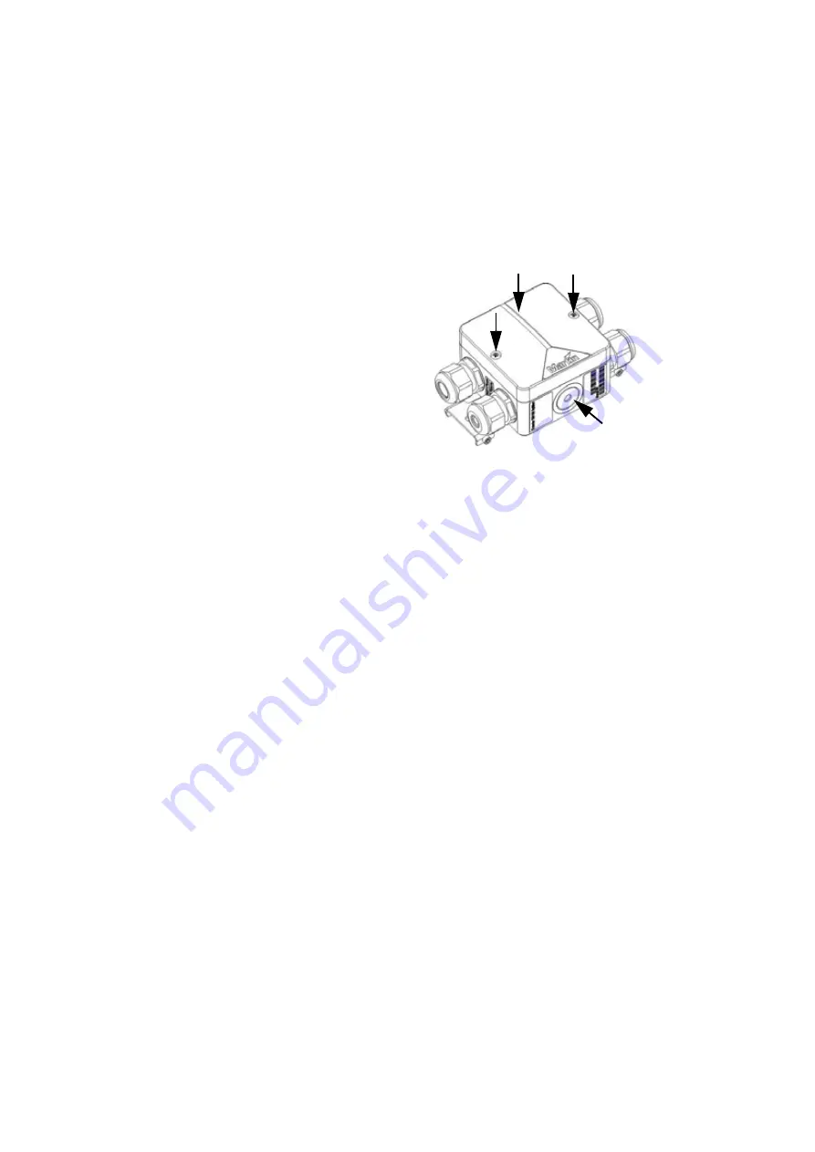
To apply sealant to a Splitter:
1. Check that all cables have 

been connected and 
connections tested.

2. See Figure 31. Place the 

Splitter either horizontal 
(with its cover 

C

 facing 

upwards) or vertical (with 
membrane 

B

 facing 

upwards).

3. Either remove the two 

screws 

A

 and lift the Splitter 

cover off or use membrane 

B

 for access, whichever will 

let you inject the sealant 
vertically downwards into the 
Splitter.

4. Install the supplied mixer 

nozzle on the sealant 
cartridge and place the cartridge in a standard caulking gun.

5. The sealant in the cartridge is a thick liquid. Fill the Splitter completely 

with sealant, allowing air to escape.

6. If you removed the Splitter cover, reinstall it, fastening both screws 

A

.

7. Allow the sealant to cure for 24 hours before exposing the Splitter to 

heavy splashing with water or immersion.

A

B

Figure 31: Access for sealant 

injection

C

A

Summary of Contents for Exterior 100

Page 1: ...Martin Exterior 50 IP68 Martin Exterior 100 IP68 System User Manual TM TM...

Page 2: ...ty for any injury damage direct or indirect loss consequential or economic loss or any other loss occasioned by the use of inability to use or reliance on the information contained in this document Th...

Page 3: ...Dimensions 3 Exterior 100 IP68 Luminaire Approximate figure allowing for cable exit 267 70 50 80 40 Z6 Standard mounting post 70 80 50 40 6 267 165 122 105 133 114 128 166...

Page 4: ...rior 50 and 100 Splitter Exterior 50 and 100 Mounting bracket bases Exterior 100 Mounting bracket Exterior 50 Mounting bracket M3 screw for mounting on DIN rail M3 screw for mounting on DIN rail 119 6...

Page 5: ...5 Exterior 50 and 100 PSU EU model 50 60 Hz DMX Power Line 1 DMX Power Line 2 Line 2 DMX Line 2 DMX Line 1 100 240VAC 100 240VAC Line 2 100 240VAC 100 240VAC Line 1 146 121 4x M3 screws DIN 912 2 5 35...

Page 6: ...6 Martin Professional Exterior 50 100 system user manual 355 328 65 70 90 161 186 Exterior 50 and 100 PSU US model 60 Hz 186 161 65 355 328 70 90...

Page 7: ...r 44 Installing Luminaires 49 Physically installing Luminaires 49 Connecting Luminaires 54 Installing light shields 59 Checking and monitoring the installation 60 System status indicators in a PSU 60...

Page 8: ...isk LED product according to EN 62471 Do not view the light output with optical instruments or any device that may concentrate the beam If you have questions about how to operate the system safely ple...

Page 9: ...m 9 8 ft luminaire cable supplied pre installed is too short extend it only with the extension cable kit available from Martin Use only the hybrid combined power and data Splitter cables supplied by...

Page 10: ...inaires or any combination within these limits where three Exterior 50 Luminaires is equivalent to one Exterior 100 Luminaire to one PSU Do not allow any chain of devices linked by hybrid Splitter cab...

Page 11: ...may concentrate the beam When installing devices overhead ensure that the supporting structure and all hardware used can hold the weight of all the devices they support plus an adequate safety margin...

Page 12: ...rtin website at www martin com Comments or suggestions regarding this document may be e mailed to service martin dk or posted to Technical Documentation Martin Professional A S Olof Palmes All 18 DK 8...

Page 13: ...a Power Supply Unit in an IPX7 rated housing that supplies the Exterior 50 100 system with 30 VDC power The PSU also relays DMX and RDM Remote Device Management data from a controller console or PC r...

Page 14: ...y isolated Martin DMX 5 3 Splitter P N 90758140 or Martin RDM 5 5 Splitter P N 90758150 installed in a dry location You must connect only one PSU directly to the DMX OUT data throughput in a PSU but y...

Page 15: ...pplier will be happy to provide guidance Data link DMX termination Each time you end a data link to a PSU a single Splitter or a daisy chain of Splitters i e you do not continue that link to another P...

Page 16: ...r Any combination of Exterior 50 and Exterior 100 Luminaires within these limits where three Exterior 50 Luminaires are equivalent to one Exterior 100 Luminaire Warning Respect the following maximum l...

Page 17: ...naire up to 18 W is the equivalent of three Exterior 50 up to 6 W Luminaires in terms of power consumption and current draw see Figure 1 Figure 1 Power and current equivalence Exterior 100 IP68 Exteri...

Page 18: ...er is supplied to the PSU via DMX cable Combined 30 VDC power and DMX data from the PSU is supplied to one to two Exterior 50 or Exterior 100 Luminaires via their supplied luminaire cables Exterior 50...

Page 19: ...m HYBRID CABLE HYBRID CABLE HYBRID CABLE HYBRID CABLE FROM PREVIOUS SECTION Exterior 100 IP68 Exterior 100 IP68 Exterior 100 IP68 Exterior 100 IP68 Exterior 100 IP68 Exterior 50 100 Splitter Exterior...

Page 20: ...naires via their supplied luminaire cables Multiple group system layout Figure 4 on the next page shows a system layout with multiple groups In a multiple group system AC mains power is supplied to th...

Page 21: ...gure 4 Multiple group system layout A larger version of this diagram is available on the After Sales Product Support pages for the Exterior 50 and 100 at www martin com Max permitted total current dra...

Page 22: ...ers can be used to link Luminaires to a PSU until the maximum safe number of Luminaires per PSU output or per PSU is reached see System layout limits on page 16 The hybrid Splitter cables and luminair...

Page 23: ...Figure 5 Loosen but do not remove compression nut F on the cable gland Pass the cable through the gland D and cable entry C until the cable jacket has passed completely through the cable gland assemb...

Page 24: ...23 Loosen but do not remove compression nut F on the unused cable gland insert a suitably sized blanking plug fully into the cable gland then hold cable entry C to prevent the assembly from rotating...

Page 25: ...f 13 m 42 6 ft total from Splitter to Luminaire To connect cables using the cable connection box follow the instructions provided with the box Note that you must Use the connections box when extending...

Page 26: ...e that have the same color and markings see Table 1 When you have finished making connections close the connections box as directed in the supplied instructions fastening it tightly with two cable tie...

Page 27: ...27 Installing Power Supply Units Physically installing a PSU Exterior 50 100 PSUs must be fastened to a flat surface See Figure 8 Figure 8 Mounting a PSU 4 x M5 screws 343 65 355 341 45 5 5 5 5 8 10...

Page 28: ...s and hardware must be capable of supporting ten times the load they will bear when devices are installed and suitable for the installation environment If you are not installing the PSU horizontally i...

Page 29: ...heck that the system is isolated from AC mains power and that power cannot be reapplied during work on the system 2 Remove the two screws arrowed from the outer cover and hinge the cover open 3 Remove...

Page 30: ...ower cable specifications listed on page 9 in the Protection from electric shock section must be used to connect the Exterior 50 100 PSU to an AC mains power source and to interconnect PSUs if you cre...

Page 31: ...system Pin Marking Screw color black brown live L yellow or brass white blue neutral N silver green yellow green ground protective earth or or PE green Table 2 Power plug pin and power cable wiring id...

Page 32: ...f the insulation from the ground earth the neutral and the live wires and install 10 mm 0 4 ins ferrules I type end caps on the ends of the wires 6 See Installing a cable in a cable gland on page 23 P...

Page 33: ...ype end caps is recommended 3 See Installing a cable in a cable gland on page 23 Pass the power throughput cable through the cable gland marked 100 240 VAC Line 2 on the PSU 4 See Figure 10 Connect th...

Page 34: ...Check that the system is isolated from AC mains power and that power cannot be reapplied during work on the system 2 See Figure 11 Prepare the data input cable for connection to the PSU by stripping t...

Page 35: ...le to the terminals marked DMX IN in the PSU as follows Connect the data shield ground conductor to the terminal marked GND Connect the data ve hot wire to the terminal marked DMX Connect the data ve...

Page 36: ...r in the unused DMX OUT terminals so that it bridges the DMX and DMX terminals Install a blanking plug in the unused cable gland marked DMX Line 2 see Installing a blanking plug in an unused cable gla...

Page 37: ...ta ground common the data ve hot and data ve cold wires The use of ferrules I type end caps is recommended 3 Install the DMX data throughput cable in the first PSU using Connecting a PSU to DMX contro...

Page 38: ...ed by Martin to the required length If you do this you must prepare custom cables for connection inside the PSU See Figure 14 strip 80 mm 3 1 ins of the outer cable jacket from the end of the cable st...

Page 39: ...the terminal marked DMX Connect the green data ve cold wire to the terminal marked DMX Connect the white 30 V ve hot wire to the terminal marked U Connect the black 30 V ve cold wire to the terminal...

Page 40: ...able gland on page 24 7 If you are going to create a second hybrid link from the PSU to a Splitter or Luminaire follow the above instructions for the second hybrid cable connecting the wires to the OU...

Page 41: ...er the connectors or it will be impossible to seal correctly Reinstall all four inner cover screws securely After accessing the terminals and indicator LEDs inside a PSU 1 See Figure 17 Check that all...

Page 42: ...itter Exterior 50 100 Splitters can be fastened to a flat surface see Figure 18 or mounted on DIN rail see Figure 19 Supporting surfaces fasteners and hardware must be capable of supporting ten times...

Page 43: ...Installing Splitters 43 Figure 19 Mounting a Splitter on DIN rail M3x10 screws supplied 4 mm screws not supplied 35 mm DIN rail not supplied 35 25 1 7 15 5 7 5 130 150...

Page 44: ...p cover and lift the cover off the Splitter housing for access to the terminals and fuse 3 After you have finished connecting and testing the Splitter check that mating surfaces are clean and undamage...

Page 45: ...er cannot be reapplied during work on the system 2 See Figure 21 Prepare a suitable length of Martin hybrid Splitter cable for connection to the Splitter strip 60 mm 2 4 ins of the outer cable jacket...

Page 46: ...a cable in a cable gland on page 23 Pass the hybrid Splitter cable through one of the hybrid larger cable diameter cable glands on the Splitter as shown in Figure 21 4 See Figure 22 Connect the wires...

Page 47: ...ata shield DMX GND Green Data ve DMX Red Data ve DMX LUMINAIRE CABLE PINOUT Wire marking Signal Terminal Black 1 red 30 VDC U Black 2 blue 30 VDC U Black 3 no mark Data ve DMX Black 4 yellow Data ve D...

Page 48: ...in out terminals and passing the cable through the unused Splitter hybrid cable gland 8 To connect Luminaires to a Splitter see the next section of this guide Figure 23 Terminating hybrid link in Spl...

Page 49: ...Luminaires Luminaires can be installed on a surface on DIN rail or on a mounting post including a ground stake that is pushed into the ground to anchor it securely Fastening to a surface An Exterior 5...

Page 50: ...fessional Exterior 50 100 system user manual 4 Check that the Luminaire is held securely and cannot fall Figure 24 Fastening to a surface M5 threaded rod Exterior 50 Exterior 100 M5 screw M5 screw M5...

Page 51: ...l the hardware to be installed on it 2 Hook the upper edge of the profile in the Luminaire mounting bracket over the DIN rail and swing the mounting bracket down so that it hangs flat against the DIN...

Page 52: ...urfaces must provide a stable support Luminaires are fastened to mounting posts and ground stakes using the same method To fasten a Luminaire mounting bracket to a mounting post 1 Check that the mount...

Page 53: ...ufficient strength to hold the Luminaire plus an adequate safety margin for the location 3 Fasten the Luminaire mounting bracket to the end of the post adjusting orientation before tightening the atta...

Page 54: ...Figure 27 and cable entry and layout are shown in Figure 28 1 2 3 4 Figure 27 Luminaire cable wire markings Red Blue No colored marking Yellow Wire marking Function Black 1 red 30 VDC Black 2 blue 30...

Page 55: ...t the wires from the luminaire cable to either of the luminaire cable terminals in the Splitter as follows Connect the 30 V ve hot black wire marked 1 with the red ring to the terminal marked U Connec...

Page 56: ...res installing the unused luminaire smaller diameter cable gland on the luminaire cable and connecting the wires in the luminaire cable to the unused luminaire cable terminals If you have finished mak...

Page 57: ...sealant is self healing This means that you can push a screwdriver through it for example and it will reseal itself It is possible to remove the sealant after applying it if you need full access to t...

Page 58: ...brane B for access whichever will let you inject the sealant vertically downwards into the Splitter 4 Install the supplied mixer nozzle on the sealant cartridge and place the cartridge in a standard c...

Page 59: ...beam angles To install a shield on the front of a Luminaire see Figure 32 Fasten the four Allen screws that are supplied with the shield through the shield and into the holes provided in the sides of...

Page 60: ...30 V power transmission at output 1 Power 2 lights red indicates 30 V power transmission at output 2 Power lights red indicates that AC mains power is present at the input Link flashes green indicate...

Page 61: ...received is outside the 20 40 V acceptable range Voltage flashes yellow identifies the DC power voltage received Long flashes indicate multiples of 10 Short flashes indicate single digit Example Volta...

Page 62: ...dress also known as the control address or start channel is the first of these channels Each fixture uses this channel and the channels immediately above it to receive instructions Exterior 50 100 Lum...

Page 63: ...This means that hue saturation intensity and white color temperature can vary slightly between Luminaires In Raw mode color output is controlled using four RGBW DMX channels The white LED control chan...

Page 64: ...Remote Control mode in Luminaire B Sign Stores configuration and exits Remote Control mode in Luminaire C Esc Exits Remote Control mode in Luminaire without storing configuration Numeric keypad 1 0 En...

Page 65: ...status indicator LED incorporated in the sensor begins to flash green and the Luminaire gives three slow flashes yellow in RGBW Luminaires 3 See Figure 37 Note the last four digits of the Luminaire s...

Page 66: ...inaire s DMX address To set a Luminaire s DMX address with the remote control unit 1 Set the Luminaire to Remote Control mode see previous section 2 Press to enter DMX Address Setting mode 3 Enter the...

Page 67: ...the intensity of the selected LEDs in RGBW Luminaires or all LEDs Sets all luminaires to zero intensity Sets all luminaires to full intensity 5 When you have programmed the scene press Sign to store...

Page 68: ...ft gives a list of the RDM compliant devices on the data link in this example one Exterior 100 and one Exterior 50 are present on the link and both are set to DMX address 1 To set Luminaires DMX addre...

Page 69: ...calls up data for that Luminaire Clicking on the Change personality button arrowed on right in this window lets you select Mode 1 Calibrated RGB or Mode 2 Raw RGBW for the Luminaire DMX footprint is u...

Page 70: ...rol of an Exterior 50 100 installation over the DMX data link using a DMX controller or a PC running DMX controller software such as the Martin M PC application If Luminaires have been set up with ind...

Page 71: ...ries you can create them in a few seconds Once you have profiles in the M PC fixture library you can control Exterior 50 100 Luminaires via DMX using a Windows PC running M PC and connected to the dat...

Page 72: ...ual Figure 41 shows the M PC DMX control interface for an Exterior 100 In this example the Luminaire is in Raw uncalibrated RGBW mode Red output is set to 5 Green is set to 10 Blue is set to 30 and Wh...

Page 73: ...Channel Value Percent Function 1 0 255 0 100 Red Intensity 0 100 2 0 255 0 100 Green Intensity 0 100 3 0 255 0 100 Blue Intensity 0 100 Start code 0 Channel Value Percent Function 1 0 255 0 100 Red In...

Page 74: ...use surface damage To clean a device in the Exterior 50 100 system 1 Disconnect the system from power and allow it to cool for at least 5 minutes 2 Clean the outside of the device with a soft cloth sl...

Page 75: ...the same type that are powered on and connected via the DMX link 2 Upload the Luminaire software as described in the Uploader application s help file or user documentation 3 Disconnect the uploader ha...

Page 76: ...aged cables Incorrect Luminaire addressing Check that Luminaire is set to correct DMX mode Check number of channels required by Luminaire s DMX mode and check Luminaire addresses Luminaire defective H...

Page 77: ...t 59 mm 2 3 in Weight 230 g 8 1 oz Exterior 50 100 Power Supply Unit EU model Length 355 mm 14 0 in Width 146 mm 5 7 in including cable glands Height 83 mm 3 3 in Weight 2 8 kg 6 2 lbs Exterior 50 100...

Page 78: ...Installation Orientation Any Mounting Surface mount 35 mm DIN rail mounting post ground stake Minimum distance from Luminaire to combustible surfaces illuminated 10 cm 4 in Maximum Splitter hybrid ca...

Page 79: ...applies to system with US model PSU UL 1310 1598 UL 8750 Included Items Included with Luminaire 3 m 9 8 ft luminaire hybrid cable pre installed Adjustable mounting bracket Included with Splitter Blank...

Page 80: ...r link hybrid cable 50 m 164 ft P N 90510180 Exterior 50 100 Splitter link hybrid cable 100 m 328 ft P N 90510190 Hybrid cables carry both power and data Related Items Martin M PC Pro up to 64 DMX uni...

Page 81: ...xterior 100 IP68 CW Narrow P N 90510020 Exterior 100 IP68 CW Medium P N 90510030 Exterior 100 IP68 NW Narrow P N 90510040 Exterior 100 IP68 NW Medium P N 90510050 Exterior 100 IP68 WW Narrow P N 90510...

Page 82: ......

Page 83: ......

Page 84: ...www martin com Olof Palmes All 18 8200 Aarhus N Denmark Tel 45 8740 0000 Fax 45 8740 0010...

Reviews: